INSTALLATION INSTRUCTIONS
R−410A, Two−Stage Split System Air Conditioner
421 01 6002 01
13
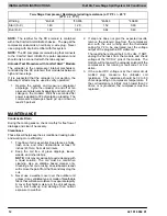
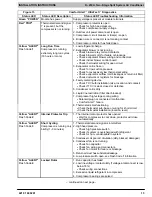
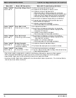
Figure 13
Comfort Alert
t
UltraTech
t
Diagnostics
Status LED
Status LED Description
Status LED Troubleshooting Information
Green “POWER”
Module has power
Supply voltage is present at module terminals
Red “TRIP”
Thermostat demand signal
Y is present, but the
compressor is not running
1. Compressor protector is open
•
Check for high head pressure
•
Check compressor supply voltage
2. Outdoor unit power disconnect is open
3. Compressor circuit breaker or fuse(s) is open
4. Broken wire or connector is not making contact
5. Compressor contactor has failed open
Yellow “ALERT”
Flash Code 1
Long Run Time
Compressor is running
extremely long run cycles
(18 hours or more)
1. Low refrigerant charge
2. Evaporator blower is not running
•
Check blower relay coil and contacts
•
Check blower motor for failure or blockage
•
Check evaporator blower wiring and connectors
•
Check indoor blower control board
•
Check thermostat wiring for open circuit
3. Evaporator coil is frozen
•
Check for low suction pressure
•
Check for excessively low thermostat setting
•
Check evaporator airflow (coil blockages or return air filter)
•
Check ductwork or registers for blockage
4. Faulty metering device
•
Check TXV bulb installation (size, location, and contact)
•
Check if TXV is stuck closed or defective
5. Condenser coil is dirty
6. Liquid line restriction (filter drier blocked)
7. Compressor high−stage cooling wiring
•
Solenoid plug not connected / malfunction
•
Comfort Alert
failure
8. Thermostat is malfunctioning
•
Check thermostat sub−base or wiring for short circuit
•
Check thermostat installation (location, level)
Yellow “ALERT”
Flash Code 2
Internal Protector Trip
1. The internal motor protector has opened
•
Wait for compressor to cool down, protector will close
automatically
Yellow “ALERT”
Flash Code 3
Short Cycling
Compressor is running only
briefly (1−3 minutes)
1. Thermostat demand signal is intermittent
2. High head pressure
•
Check high pressure switch
•
Check if system is overcharged with refrigerant
•
Check for non−condensable in system
3. Condenser coil poor air circulation (dirty, blocked, damaged)
4. Condenser fan is not running
•
Check fan capacitor
•
Check fan wiring and connectors
•
Check fan motor for failure or blockage
5. Return air duct has substantial leakage
6. Low pressure switch open, see Flash Code 1 information
Yellow “ALERT”
Flash Code 4
Locked Rotor
1. Run capacitor has failed
2. Low line voltage (contact utility if voltage at disconnect is low,
below 187v)
•
Check wiring connections
3. Excessive liquid refrigerant in compressor
4. Compressor bearings are seized
− continued on next page −


