


1
1
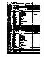
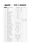
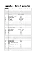
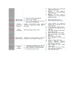
Function And Description
Setting Range
Unit
Remarks
max speed
50
800
rpm
speed 1
100
800
rpm
Speed 2
150
800
rpm
speed 3
200
800
rpm
trimming after urgentstop
1 Yes, 0 No
top needle stop position
1
4319
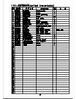
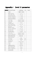
check frequency
15~ 45
stretching time
150~ 1000
presser foot put down time
150~ 500
thread trim switch
0 off , 1on
needle bar lift angle
-120--120
winding speed
100
800
rpm
back to origin speed
1~ 4
1,slow
4 quick
empty feeding speed
1~ 9
1, slow
9 quick
patterning speed
1~ 5
1, slow
5 quick
foot up after Sew stop
0no 1 yes
Air pressure detect switch
0 off 1 on
Pressure testing of
0invariant 1negation
Add Trim when NOP MOVE
0no 1yes
pressure box up when trim
0no 1yes
path of return origin 2
0 path 1 direction
sweeping thread switch
0off 1on
urgent stop switch polarity
0invariant 1negation
Breakage detection switch
0 close 1 open
thread loosing switch
0off 1on
sweeping thread time
50---2000
auto trim after sew end
0no 1yes
perm down check(0-1)
0 1
perm sensor polarity(0-1)
0 1
Breakage detection polarity
0Unchanged 1Inverse
thread trim
0later 1immediate
pattern input
0manual 1scanned
stopping position
0
origin 1
unoriginal
bottom line detection switch
0off 1on
cop latch length unit mm
1000~ 65000
Dowel pin install location
0~ 800
needle down position
0~ 800
Summary of Contents for GA204-107
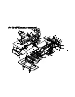
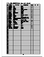
Page 1: ...BT 11020 RP TB PARTS INSTRUCTION MANUAL...
Page 8: ...00 1 2 3 4 5 2 50 054 5 652257 5 58 9 5 4 4 57 22 4 5 3 257...
Page 9: ......
Page 10: ...0 1 2 3 4 2 3 4 3 5 6 503 7 3 4 8 3 9 9 2 5 5 0 0 5 0 5 5 3...
Page 11: ......
Page 12: ......
Page 13: ......
Page 14: ......
Page 15: ......
Page 16: ......
Page 17: ......
Page 18: ......
Page 19: ......
Page 20: ......
Page 21: ......
Page 22: ......
Page 23: ......
Page 24: ......
Page 25: ......
Page 26: ......
Page 27: ......
Page 28: ......
Page 29: ......
Page 30: ......
Page 31: ......
Page 32: ......
Page 33: ......
Page 34: ......


