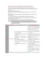
operates per the position command pulse
or not. See the torque monitor to check if
the output torque is saturated. Readjust
the gains.
Maximize the value of Pr12 (torque limit
set-up). Correct the encoder wiring per
the wiring diagram. Increase the
acceleration and deceleration time.
Reduce the load and velocity.
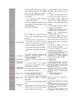
Err
12
CW
over-travel
limits
The CW over-travel limits is not
Active.
Check the switches, wires and power
supply that constitute the circuits... Check
the value of Pr59. Correct the wiring, if
necessary.
Err
13
CCW over-travel
limits
The CCW over-travel limits are not
Active.
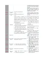
Err
14
Overload
Overload protection is activated via the
specified time limiting operation when the
integration of a torque command exceeds the
specified overload level. Caused by a long
operation with a torque that exceeds the
specified torque limit.
1) Long operation with more load and
Torque than the rating.
2) Vibration or hunting due to incorrect gains.
Cause vibration and/or abnormal sound.
3) Motor wires connected wrong or broken
4) The machine is hit against a heavy hing, or
suddenly becomes heavy in operation. The
machine is en tangled.
5) The electromagnetic brake is ON.
6) In a system of multiple drivers, some
motors are wired incorrectly to other axis.
Monitor the torque (current wave) using
an oscilloscope to check whether the
torque is surging or not. Check the load
factor and overload alarm messages.
1) Increase the capacity of the driver and
motor. Lengthen the ramp time of
acceleration/ deceleration. Reduce the
motor load.
2) Readjust the gains.
3) Correct the motor wiring per the wiring
diagrams. Replace cables.
4) Free the machine of any tangle.
Reduce the motor load.
5) Measure the voltage at the brake
wiring connections. Turn off the brake.
6) Correct the motor and encoder wiring
to eliminate the mismatching between
the mo.
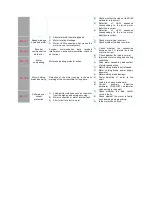
Err
15
Module Fault
If power on again and the fault is still
existence, please replace with a new
driver.
Err
16
Energy witching
timeOut
Servo drive works in the energy consumption
braking state for a long time.
1) Test the servo drive R,S,T input
terminal voltage is too high.
2) Check
whether
the
energy
consumption brake resistance is
normal and the terminals are in good
contact.
3) Check whether the Pr6B and Pr6C
parameter values are set too small.
Err
18
Encoder signal
anomaly
1) Encoder signal receives interferences.
2) Encoder receives exception information.
1) Check whether the encoder wiring is
good and reliable.
2) Check the encoder cable wiring is
reasonable (such as with the motor
power cord or other large current
cable wrapped together).
3) Motor encoder damage.
Err
19
Error of current
detection
Detection of zero current anomaly.
1) To confirm whether the current zero
drift is too large.
2) According to the manufacturer to
guide
the
implementation
of
automatic zero calibration.
Err
20
Motor over
speed
1) Motor speed exceeds the maximum
limit..
2) Abnormal motor operating speed.
1) Check whether the value of the Pr73
parameter is too small for the limit
value of the speed limit.
Summary of Contents for GA204-107
Page 1: ...BT 11020 RP TB PARTS INSTRUCTION MANUAL...
Page 8: ...00 1 2 3 4 5 2 50 054 5 652257 5 58 9 5 4 4 57 22 4 5 3 257...
Page 9: ......
Page 10: ...0 1 2 3 4 2 3 4 3 5 6 503 7 3 4 8 3 9 9 2 5 5 0 0 5 0 5 5 3...
Page 11: ......
Page 12: ......
Page 13: ......
Page 14: ......
Page 15: ......
Page 16: ......
Page 17: ......
Page 18: ......
Page 19: ......
Page 20: ......
Page 21: ......
Page 22: ......
Page 23: ......
Page 24: ......
Page 25: ......
Page 26: ......
Page 27: ......
Page 28: ......
Page 29: ......
Page 30: ......
Page 31: ......
Page 32: ......
Page 33: ......
Page 34: ......

