background image

!"#$% &'()

*+,- &'()

! "

!"#$ %&'( )* +),-"'. ' ,#+/&$'

!

Summary of Contents for GA204-107

Page 1: ...BT 11020 RP TB PARTS INSTRUCTION MANUAL...

Page 2: ...djusting zero position 34 2 2 1 Adjusting the position of the induction rion for the sensor of the needle upper position 34 2 3 Basic operation 35 2 4 Transfering patterns by a USB disk 38 2 5 Adjusti...

Page 3: ...ation Table 65 Accessories 1 Accessories of the machine head 1 Thead stand 1Set 7 Hexagon apanner 1Set 13 ScrewM5X12 9Pcs 2 Hinge 2Sets 8 Oil can 1Pc 14 Nut M5 9Pcs 3 Rubber wasger 4Pcs 9 Needle 5Pcs...

Page 4: ...8 45 4 4 7 91 4 4 I 7 23 3 3 28 7 JK 8 22 39 LM A 0 7 4N173 4 892 3 8 392 O 924 39 3 9 2 6 3 17 2 77 3 JK 8 22 39 LM 892 17 6 7 2 81 2 4 P 3 P 1 0 2 4 Q 4 2 1 4 2 277 2 8992 C 5 2 P 7 5 7 4 P 73 3 3 7...

Page 5: ...44 2 86 B2 H7 4 2 42 2 67 2 6 44 D C F G 4 6 44 A2 2 B2 6 44 42 2 B B 8 F G 4 6 2 4 2 2 8 I 66 7 G 4 4 2 4 C 3 2 6 44 6 D E F G 4 42 2 8 C A2 6 4 0 12 2 3 4 6 6 4 4 2 66 2 2 4 5 C J D E F G 4 2 42 6 B...

Page 6: ...3 4 3 2 9 4 H 4I3 0 2 9 7J 0 0 5 D2 0 5 3 6 4I3 4 92 2 0 4055 5 D 0K 0 6 4I3 0 2 63 5 3 J 43 0 L L D3 0 790 0 2 3 8 3 790 43 2 3 D2 0 5 0 40 4 2 40 5 2 M055 2 3 4 2 2 4055 N0 N0 O P 4I3 2 3 5 5 0 40...

Page 7: ...0 1 2 0300 45 61 0300 3 3 0300 4 7 85 9 4 7 4 37 4 4 43 4 3 5 4 4 1 43 0300 4 3 0 443 4 3 13 4 4 5 A 37 0300 4 3 1 0300 1 4 B 11 4 4 3 11 5 C3 D 3 37 4 3 3 3 0300 3 1 0 E 37 FGH 37 0300 5 6 5 I...

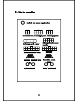
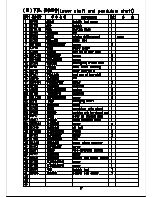
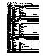
Page 8: ...00 1 2 3 4 5 2 50 054 5 652257 5 58 9 5 4 4 57 22 4 5 3 257...
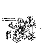
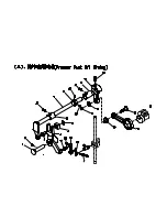
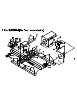
Page 9: ......

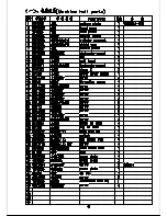
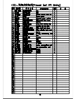
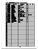
Page 10: ...0 1 2 3 4 2 3 4 3 5 6 503 7 3 4 8 3 9 9 2 5 5 0 0 5 0 5 5 3...
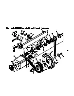
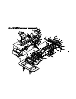
Page 11: ......

Page 12: ......

Page 13: ......

Page 14: ......

Page 15: ......

Page 16: ......

Page 17: ......

Page 18: ......

Page 19: ......

Page 20: ......

Page 21: ......

Page 22: ......

Page 23: ......

Page 24: ......

Page 25: ......

Page 26: ......

Page 27: ......

Page 28: ......

Page 29: ......

Page 30: ......

Page 31: ......

Page 32: ......

Page 33: ......

Page 34: ......

Page 35: ...ure detect switch 0 off 1 on Pressure testing of 0invariant 1negation Add Trim when NOP MOVE 0no 1yes pressure box up when trim 0no 1yes path of return origin 2 0 path 1 direction sweeping thread swit...

Page 36: ...16 Thread loose open time 1 180 P 17 pressurebox width check mm 300 300 P 18 presser foot up time 50 2000 P 19 main shaft start time 40 1000 P 20 presserfoot max height 30 200 mm P 21 z sensor polarit...

Page 37: ...ratio 600000 50000000 P 16 Y motor transmission ratio 600000 50000000 P 17 stretch presser foot up time 40 500 P 18 change the needle time 150 500 P 19 motor rotation direction 0invariant 1negation P...

Page 38: ...specified value 1 The driver failed due to defective circuits or IGBT parts 2 Motor wires U V and W are shorted 3 Motor wires U V and W are grounded Motor burned 5 Poor connection of Motor wires 6 Th...

Page 39: ...ck the timing of power on for both the main power and control power Err 04 Over heat The radiator is heated up to exceed the limit temperature The power elements of the driver are overheated Overload...

Page 40: ...ase the capacity of the driver and motor Lengthen the ramp time of acceleration deceleration Reduce the motor load 2 Readjust the gains 3 Correct the motor wiring per the wiring diagrams Replace cable...

Page 41: ...al Err 24 Motor overheating Motor overheating protector action 1 Improved motor cooling and cooling conditions 2 False alarm caused by bad contact of motor encoder line Err 25 Motor holding break abno...

Reviews: