11. BATTERY
,
CHARGING SYSTEM
11-4
Battery
Remove
Note:
Keep the ignition switch at OFF before operation.
Remove:
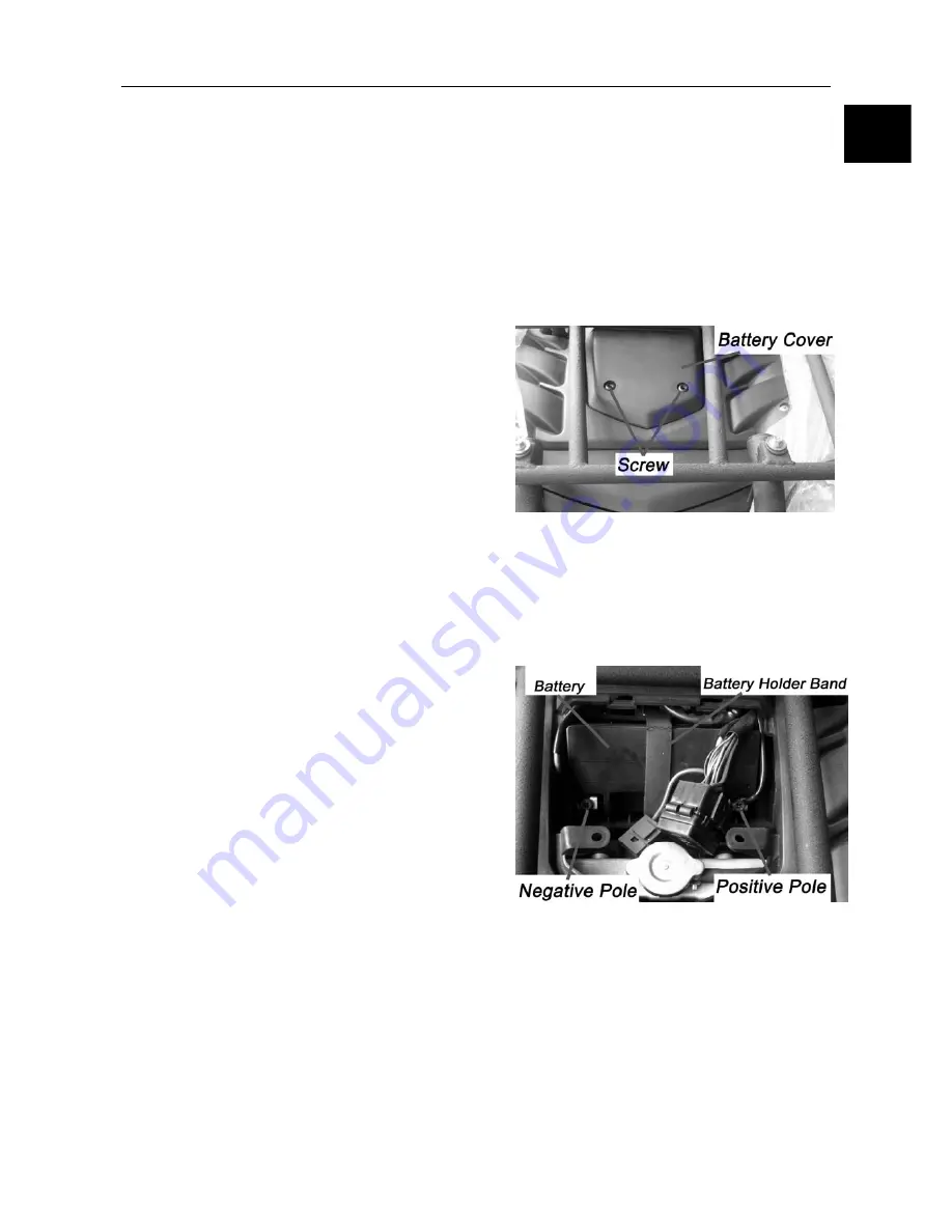
Remove the two screws and the battery cover.
Remove the
holder
band of battery.
Loosen negative pole screw and disconnect.
negative lead.
Remove positive pole cap and screw.
Disconnect positive lead
Remove battery.
Installation:
Reverse the removal procedure for installation.
Note:
Apply clean lubricant grease to the pole after
installation.
Install cap firmly on the positive pole after installation.
Inspection:
Measure voltage between battery terminals, and
check test status.
Complete test: 12.8V
Insufficient test: <11.8V
Insufficient charge: Recharge
Note:
When recharging after normal charging, measure
the voltage between terminals after 30 minutes.
Measuring immediately after recharging will not gain
the correct test due to the sharp voltage changes
between the terminals.
Battery
Note:
Usually no hydrogen will be generated during
charging except when overcharged. Keep away
from fires when charging.
Charge according to the current and time specified
on the label of battery.
11
Summary of Contents for 500ATV
Page 1: ...Service Manual 500ATV 500ATV 2 4 4 ...
Page 16: ...1 SERVICE INFORMATION 1 14 ...
Page 17: ...1 SERVICE INFORMATION 1 15 1 ...
Page 18: ...1 SERVICE INFORMATION 1 16 ...
Page 32: ...2 Vehicle body Muffler 2 14 Visible Parts ...
Page 53: ...4 COOLING SYSTEM 4 7 Cooling System Chart 4 ...
Page 63: ...6 Engine Removal Inspection Installation 6 1 Wu Yang 500 CC engine maintenance manual 6 ...
Page 71: ......
Page 72: ......
Page 73: ...6 Engine Removal Inspection Installation 6 11 Engine information 6 ...
Page 190: ...11 BATTERY CHARGING SYSTEM 11 9 Layout for All Electricity Equipment in Vehicle ...
Page 192: ...12 IGNITION SYSTEM 12 2 Ignition System Diagram ...
Page 200: ...12 IGNITION SYSTEM 12 10 Layout for Ignition System Equipment in Vehicle ...
Page 212: ...13 Lighting Instruments Switches 13 12 500ATV Circuit Diagram ...


