39
G
.
.
.
.
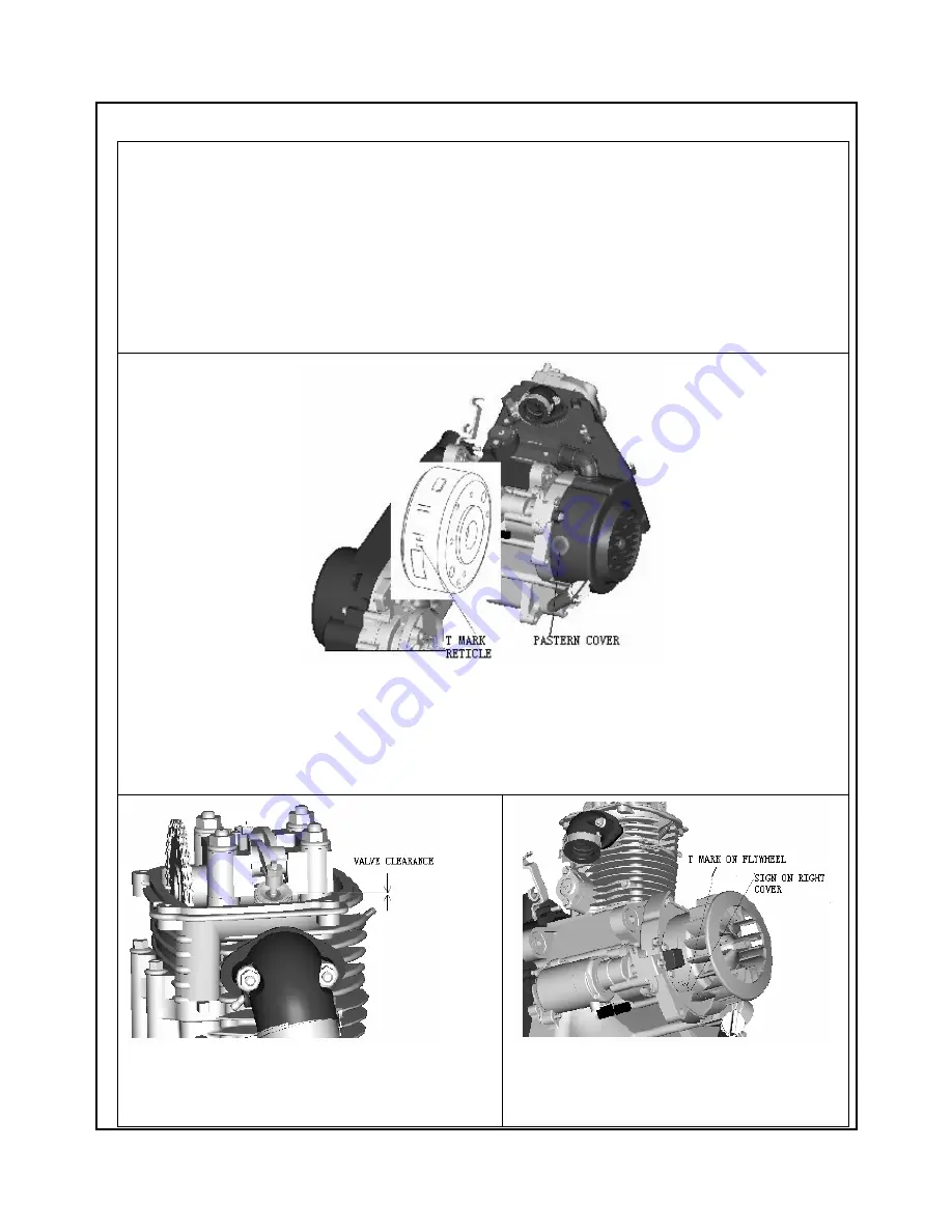
VA LV E C L E R A N C E S E T U P
Engine is in cooling state.
1
、
Remove cylinder head cover
;
2
、
Remove pastern cap of fan whorl shell.
;
3
、
Keep “T” mark on flywheel the same line with the mark on righ crankcase cover
;
4
、
Ensure timing reticle of cam sprocket in the same line with joint surface of cylinder head cover.
;
5
、
Inspect the clearance of inlet valve and exhaust valve, inlet valve
:
0.03~0.05mm
,
exhaust valve
:
0.05~0.06mm
,
if clearance is not at the range of specified volume, adjust rocker adjusting screw until the
clearance reaches its specified range.
Summary of Contents for ARN125
Page 5: ...5 A GENERAL INFORMATION...
Page 11: ...11 B PRODUCT...
Page 13: ...13 1 2 3 4 5 6...
Page 14: ...14 7 8 9 10 11 12...
Page 24: ...24...
Page 37: ...37 F Lubrication system Rocker arm Camshaft assy Crankshaft assy Oil pump assy Fileter assy...
Page 52: ...52...
Page 62: ...62...
Page 63: ...63 Charging system circuit diagram AC circuit diagram...
Page 72: ...72 C OTHERS...


