


4
2 Directions for use
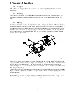
2.1
Operation
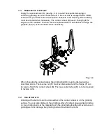
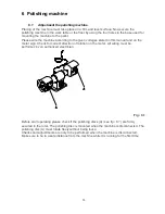
After adjustment and connection the machine is ready for use. The grinding kan take place
by the contact wheel (E) or on the surface grinding table by opening the cover (H). When
you start grinding please start by letting the material touch the grinding wheel lightly and
thereby avoid pressuring the grinding wheel to prolonge the lifetime of it. The lifetime of a
grinding belt is also prolonged if you start with a light pressure. Please make sure not to
overload the motor. Let it run at max speed before start grinding. Grind at max speed and if
possible have the material tightened in clamps as it is safer than holding the material in
your hands. Avoid grinding on the side of the grinding wheel unless you are using a cup
wheel. Do not stop the grinding wheel by pushing any material against it but let it stop by
itself. It is very important to keep the working area well lighted.
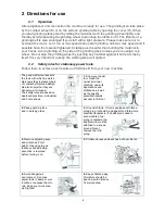
2.2
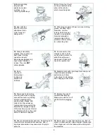
Safety rules for stationary power tools.
Follow them to achieve best results and full benefit from your new machine.
The good craftsman respects
the tools with which he works.
He knows they represent years
of constantly improved design.
He also knows that they are
dangerous if misused.
The safety rules are based on
approved practices in industrial
and home shops.
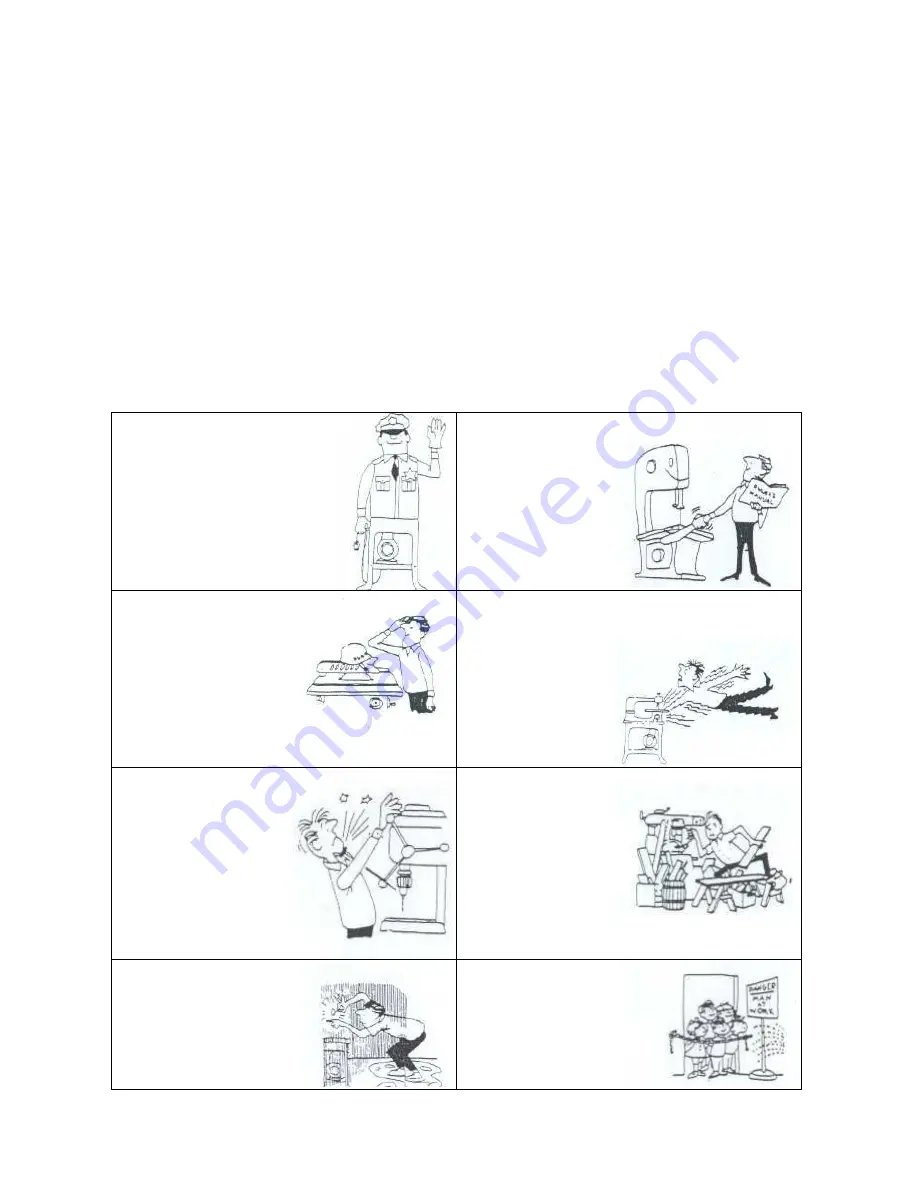
1.
Know your power
tool. Read the
owner’s manual
carefully. Learn its
applications and
limitations, as well
as the specific
potential hazards
peculiar to this tool.
2.
Keep guard in place
and in working order.
3.
Ground all tools. If tool is equipped with three-
prong plug, it should be plugged into a three-hole
electrical receptacle. If an adapter is used to
accomodate a two-
prong receptacle, the
adapter wire must be
attached to a known
ground. Never
remove the third
prong.
4.
Remove adjusting keys
and wrenches. Form
habit of checking to see
that keys and adjusting
wrenches is removed
before turning it on.
5.
Cluttered areas and benches invite accidents.
6.
Avoid dangerous
environment. Don’t use
power tools in damp or wet
locations or expose them to
rain. Keep your work area
well lighted.
6.
Keep children away.
All visitors should be
kept in a safe distance
from work area.


