

12
5.3
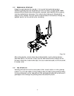
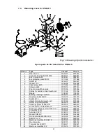
Maintenance of deburrer/steel brush
Nothing on the deburrer/steel brush needs maintenance except that it is necessary to adjust
the grinding system as the steel brush is worn. The eye shield and other accessories must
be replaced immediately if they are damaged.
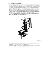
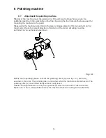
5.4
Use of deburrer
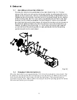
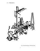
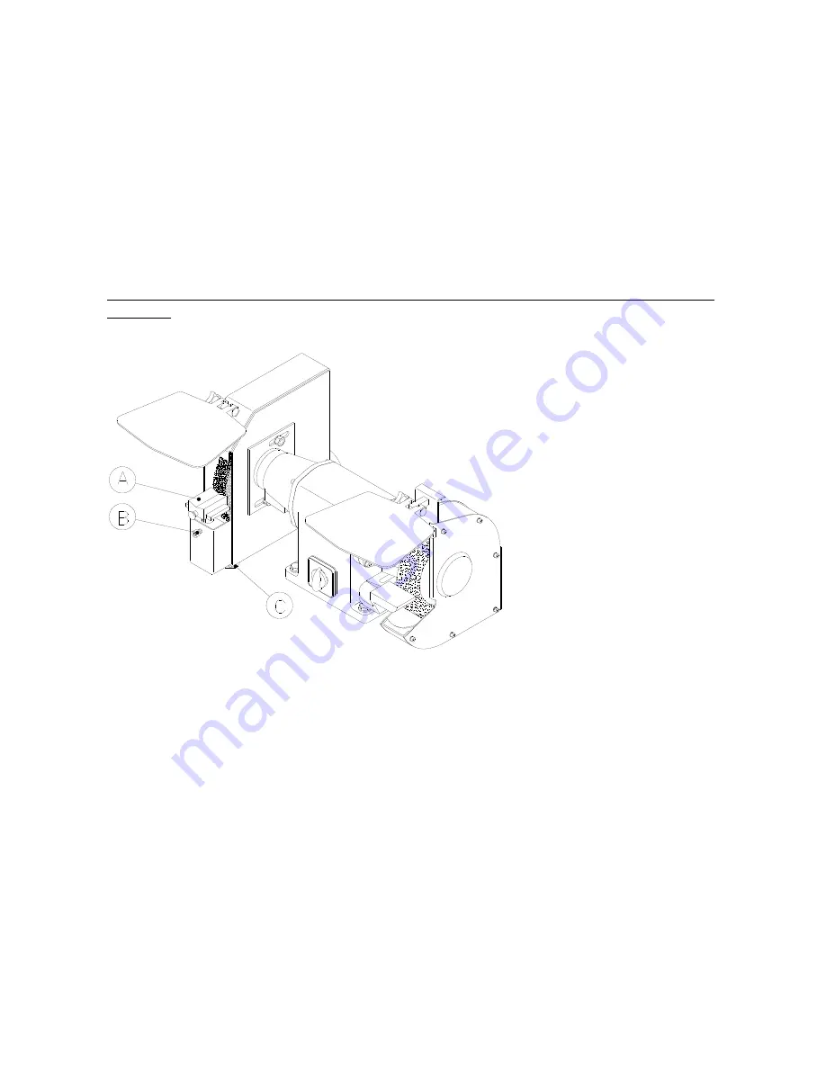
When the deburrer cover is correctly mounted the grinding system (A) (see
fig.: 5.2
) needs
adjusting which is done by adjusting the height of the grinding system when the screw (B)
is unscrewed. The distance to the steel brush is adjusted by loosening the handle (C) below
the cover. As mentioned earlier the grinding system for pipe grinding (A) can be dismounted
and the flat grinding surface beneath can be used for grinding of plate or bar material.
This adjustment of the grinding system can only be made when the machine is NOT
plugged.
Fig.: 5.2
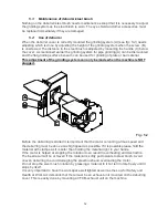
Before the deburring is started it is important that the motor is running at max speed and
the deburring must be done at as high speed as possible. If it is possible please hold the
material with clamps as it is safer than holding the material right in your hands.
If the motor is helped at stopping the rotation it can result in overheating and destruction.
The best result will be achieved if the material is softly put towards to steel brush. Avoid
uneven deburring to avoid damaging the steel brush and overloading the motor.
Do not stop the steel brush rotation by pressing a material to it but let it rotate freely until it
stops by itself.
It is very important to have the work space well lighted as well as the Law for Safety and
Health at Work Act demands that there must be an exhaust unit mounted on the deburring
cover. This is easily done by mounting a VFCB-exhaust unit on the machine.


