background image

18 


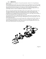
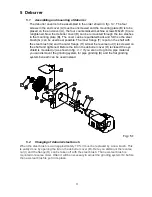
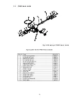
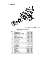
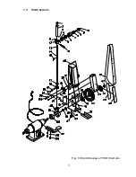
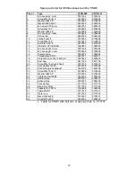
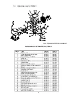
Spare parts list for PSD 5 belt arm 


Order number 

Pos. Nr. 

Type 

    Right 

Left 

Top screw 

  2078212  2078212 

Sliding pipe for belt stand 

  9480687  9480687 

Machine screw M4x4 Z 

  0737618  0737618 

Lock ring DIM 42, DIN 472 

  7655123  7655123 

Ball bearings 6302 2Z 

  1462846  1462846 

Distance pipe ø22/15x10 

  2155002  2155002 

Top roll 

  9480681  9480681 

Shaft for top roll 

  2078200  2078200 

Disc for  top roll 

  9480693  9480693 

10 

Screw M6x16 CH Z lowered head 

  0120625  0120625 

11 

Pointed screw M5x10 

  0737605  0737605 

12 

Holder for top roll 

  9480679  9480679 

13 

Spring for telescope arm 

  9480694  9480694 

14 

Pipe for telescope arm 

  9480682  9480682 

15 

Spring holder for telescope arm 

  2078202  2078202 

16 

Handle for grinding belt M8x30 

  2078204  2078204 

17 

Pipe bushing for telescope arm 

  2078206  2078206 

18 

Pipe holder for telescope arm 

  9480692  9480692 

19 

Pipe cotter pin ø5x25 

  2078208  2078208 

20 

Håndle for adjustment of grinding belt 

  2188010  2188010 

21 

Fittings for telescope arm 

  1533813  1533813 

22 

Washer DIM 8 Z 

  0132594  0132594 

23 

Screw M8x25  CH Z 

  7676512  7676512 

24 

Distance ring 

  4318001  4318001 

25 

Pointed screw M8x12 

  0105026  0105026 

26 

Holder for telescope arm 

  2078211  2078211 

27 

Grinding system 

  0744425  0744409 

28 

Disc 3/8” Z 

  0101491  0101491 

29 

Screw M10x30 Z 

  0236005  0236005 

30 

Box cover for belt arm 

  1533780  1533781 

31 

Washer DIM 5 Z 

  0102555  0102555 

32 

Screw M5x10 CH Z 

  0120628  0120628 

33 

Felt washer 

  1533816  1533816 

34 

Cover plate 

  1533812  1533812 

35 

Distance ring ø30/20x6mm 

  1551176  1551176 

36 

Collar bushing PSD 5 

  0995681  0995681 

37 

Star handle ø40 M8 DIN 6335 

  1443593  1443593 

38 

Auto disc 5/16” Z 

  5437850  5437850 

39 

Spark arrestor 

  1533808  1533808 

40 

Nut M5 Z 

  0737623  0737623 

41 

Flange inner 

  0921572  0921572 

42 

Contact wheel 200x50x20 

  1532170  1532170 

43 

Square table 

  1533807  1533818 

44 

Flange outer 

  1105183  1105183 

45 

Double sticking tape 

  2004899  2004899 

46 

Graphite pad 50x270 

  2004898  2004898 

47 

Nut M20x1.5 

  0744824  0744816 

48 

Grinding belt 

  0215080  0215080 

50 

DN-bearing ring for belt arm 

  0120510  0120510 


Summary of Contents for PSD 5

Page 1: ...Industrivej 3 9 DK 9460 Brovst Tel 45 9823 6266 Fax 45 9823 6144 25 04 12 KEF MOTOR A S Instruction Manual PSD 5 BO 50 5 POD 5 PODA 5 Industrial Grinders...

Page 2: ...nce with the provisions of the COUNCIL DIRECTIVE of 17 May 2006 2006 42 EC The Machinery Directive order no 561 of 25 June 1994 with subsequent amendments Also on accordance with The council directive...

Page 3: ...UST UNIT 10 5 POLISHING MACHINE 13 5 1 ADJUSTMENT THE POLISHING MACHINE 13 6 DEBURRER 11 6 1 ASSEMBLING AND MOUNTING OF DEBURRER 11 6 2 CHANGING OF DEBURRER STEEL BRUSH 11 6 3 MAINTENANCE OF DEBURRER...

Page 4: ...nd it is important to control that the motor and the exhaust unit have the correct direction or rotation please see the arrow on the motor Fig 1 1 Before use you must control that the outer cover A se...

Page 5: ...to achieve best results and full benefit from your new machine The good craftsman respects the tools with which he works He knows they represent years of constantly improved design He also knows that...

Page 6: ...both hands to operate tool 14 Don t overreach Keep proper footing and balance at all times 15 Maintain tools with care Keep tools sharp and clean for best and safest performance Follow instructions f...

Page 7: ...ount the outer cover B The reverse nut C and the outer flange is to be unscrewed now the outer flange and the grinding wheel can be dismounted The new grinding wheel is not allowed to exceed the measu...

Page 8: ...alloved to be fastened harder than it is still possible to adjust the direction of the grinding belt The belt arm can be tilted to the wanted inclination After this the holder for the telescopearm D i...

Page 9: ...adjust by the handle D for parallel running The belt is loosened so that the telescopearm E and top wheel F can be turned with until the grinding belt runs straightly on the contactwheel After this th...

Page 10: ...C on the belt arm when necessary Fig 3 3 When changing the contact wheel the grinding belt D must be dismounted as described above The reverse nut E must be dismounted and the flange F can be taken o...

Page 11: ...E with exhaust connecting piece also remember to mount the cork washer F Finally adjust the suction hoses G and mount the clip washers H VFCB exhaust unit must before use be mounted with suction hose...

Page 12: ...ange H At last the reverse nut I is screwed on the shaft and tightened Before the lid on the deburrer cover D is closed the eye shield is mounted J as shown in fig 4 1 If you are not to grind a pipe m...

Page 13: ...g system can only be made when the machine is NOT plugged Fig 5 2 Before the deburring is started it is important that the motor is running at max speed and the deburring must be done at as high speed...

Page 14: ...ual and on the motor sign Check for correct direction of rotation on the motor All wiring must be performec by an authorized electrician Fig 6 1 Before start operating please check if the polishing di...

Page 15: ...14 7 Spare parts In this chapter there are split drawings and matching spare parts lists 7 1 Machine line up of PSD 5 Fig 7 1 A Motorpart B Grinding cover C Belt arm D VFCB exhaust unit...

Page 16: ...ring 50x45x3 mm 1385259 6 Wave spring 50x44x0 6 0100331 7 Bearing 6205 2Z C3 0104221 8 Cable 4x0 75mm sort 0129420 9 Cable lead in PG11 0105154 10 Blind stop PG11 2112512 11 Stator housing 1313711 12...

Page 17: ...44840 0744840 9 Washer DIM 6 Z 1323060 1323060 10 Flange screw M10 1311956 1311956 11 Screw M5x10 CH Z 0120628 0120628 12 Washer DIM 5 Z 0737666 0737666 13 Lid PSD 5 cover 0745111 0745111 14 Cover PSD...

Page 18: ...17 7 4 PSD 5 belt arm Fig 7 4 Split drawing of PSD 5 belt arm...

Page 19: ...grinding belt 2188010 2188010 21 Fittings for telescope arm 1533813 1533813 22 Washer DIM 8 Z 0132594 0132594 23 Screw M8x25 CH Z 7676512 7676512 24 Distance ring 4318001 4318001 25 Pointed screw M8x...

Page 20: ...19 7 5 VFCB exhaust system for PSD 5 Fig 7 5 Split drawing of VFCB exhaust system for PSD 5...

Page 21: ...58 15 Fan housing R outer 0785636 0785636 16 Power engine 1043072 1043064 17 Thread piece PG11 0920011 0920011 18 Protection hose 18x13 400mm 0920400 0920400 19 Dust bag 0811793 0811793 20 Screw M4x16...

Page 22: ...ange 1105183 1105183 12 Bushing reducing 32 20mm 5003220 5003220 13 Steel brush 250x32x32 1531419 1531419 14 Nut M20x1 5 0744824 0744816 15 H ndle for deburrer steel brush 0110168 0110168 16 Holder fo...

Page 23: ...Spare parts list for POD 5 w flange Pos nr Type Left Right 1 Polishing guard Left 0921432 0921434 2 Disk 6mm 0737631 0737631 3 Skrew M6x10 0110089 0110089 4 Distance ring 20x30x6 1551176 1551176 5 Spi...

Page 24: ...ist for POD 5 w spindle Pos nr Type Left Right 1 Polishing guard Left 0921432 0921434 2 Disk 6mm 0737631 0737631 3 Skrew M6x10 0110089 0110089 4 Flange inner 0921572 0921572 5 Polishing Mop 200x20x 6...

Page 25: ...ass F F F Amp 1 9 3 3 1 9 3 3 1 9 3 3 Cos 0 81 0 81 0 81 Weight 38 24 The noise level for these machines varies from 76 dB A PSD 5 POD 5 to 88 dB A BO 50 5 according to the measuring directions in the...

Page 26: ...25 8 3 Wiring diagrams PSD 5 BO 50 5 and POD 5 industrial grinding machines can be wired 3 x 400 V 50 60 Hz or 3 x 230 V 50 60 Hz Please see wiring diagrams below Max Volt Max Volt...

Page 27: ...26 Disa Switch w emergency stop 8 4...

Page 28: ...27 8 5 PSD 5 connected to EX16 Dust Extraction...

Page 29: ...not been misused or carelessly handled and in particular has not been used in a manner contrary to the operating instructions 3 Repairs have not been made or attempted by other than our own Service St...

Reviews: