
2
Table of contents
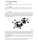
1
TRANSPORT & HANDLING
3
1.1
T
RANSPORT
3
1.2
H
ANDLING
3
1.3
P
LACING
3
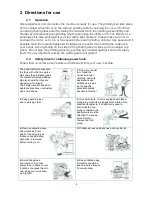
2
DIRECTIONS FOR USE
4
2.1
O
PERATION
4
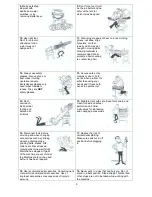
2.2
S
AFETY RULES FOR STATIONARY POWER TOOLS
.
4
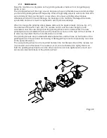
2.3
M
AINTENANCE
6
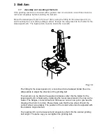
3
BELT ARM
7
3.1
A
SSEMBLY AND MOUNTING OF BELT ARM
7
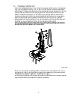
3.2
C
HANGING OF GRINDING BELT
8
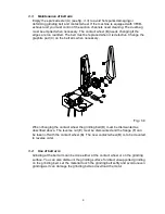
3.3
M
AINTENANCE OF BELT ARM
9
3.4
U
SE OF BELT ARM
9
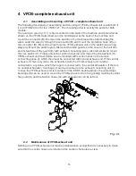
4
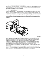
VFCB-COMPLETE EXHAUST UNIT
10
4.1
A
SSEMBLING AND MOUNTING OF
VFCB
–
COMPLETE EXHAUST UNIT
10
4.2
M
AINTENANCE OF
VFCB-
EXHAUST UNIT
10
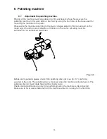
5
POLISHING MACHINE
13
5.1
A
DJUSTMENT THE POLISHING MACHINE
.
13
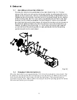
6
DEBURRER
11
6.1
A
SSEMBLING AND MOUNTING OF DEBURRER
11
6.2
C
HANGING OF DEBURRER
/
STEEL BRUSH
11
6.3
M
AINTENANCE OF DEBURRER
/
STEEL BRUSH
12
6.4
U
SE OF DEBURRER
12
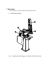
7
SPARE PARTS
14
7.1
M
ACHINE LINE UP OF
PSD
5
14
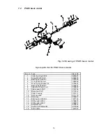
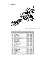
7.2
PSD
5
BASIC MODEL
15
7.3
PSD
5
COVER
16
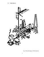
7.4
PSD
5
BELT ARM
17
7.5
VFCB-
EXHAUST SYSTEM FOR
PSD
5
19
7.6
POD
5
W
/
SPINDLE
23
7.7
D
EBURRING COVER FOR
PODA
5
21
7.8
24
8
TECHNICAL DATA
24
8.1
T
ECHNICAL SPECIFICATIONS
24
8.2
D
IMENSIONS
24
8.3
W
IRING DIAGRAM
25
8.4
D
ISA
S
WITCH W
/
EMERGENCY STOP
26
8.5
8.5
PSD
5
CONNECTED TO
EX16
D
UST
E
XTRACTION
27
8.6
G
UARANTEE
28