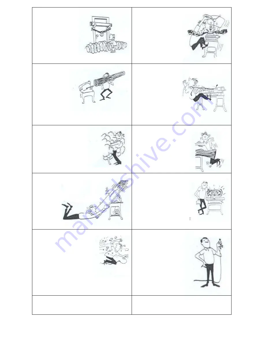
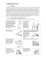
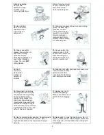
background image


8.

 Make workshop 

kidproof with 
padlocks, master 
switches, or by 
removing starter keys. 

9.


Don’t force tool. It will 

do the job better and be 
safer at the rate for 
which it was designed.  


10.

 Use right tool. 

Don’t force tool or 
attachment to do 
a job it was not 
designed for. 

11.

 Wear proper apparel. Wear no loose clothing, 

gloves, neckties, rings, 
bracelets, or other 
jewelry which may get 
caught in moving parts. 
Non-slip footwear is 
recommended. Wear 
protective hair covering 
to contain long hair. 
 

12.

 Always use safety 

glasses. Also use face or 
dust mask if cutting 
operation is dusty. 
Everyday eyeglasses only 
have impact resistant 
lenses. They are 

NOT


safety glasses. 

13.

 Secure works. Use 

clamps or vise to hold 
works, when pratical. It’s 
safer than using your 
hands and it frees both 
hands to operate tool.  
 

14.


Don’t 

overreach. 
Keep proper 
footing and 
balance at 
all times. 
 

15.

 Maintain tools with care. Keep tools sharp and 

clean for best and safest 
performance. Follow 
instructions for lubricating 
and changing accessories.  


16.

 Disconnect tools before 

servicing and when changing 
accessories such as grinding 
wheels, polishing mops, 
grinding belts, blades, bits, 
cutters, etc. Never leave a 
running maschine, wait till the 
Machine has stopped. If parts 
of the machine are out of order 
the Machine shold not be used 
befour it has been repaired. 

17.

 Reduce the risk of 

unintentional starting. 
Make sure switch is in off 
position before plugging 
in.  

18.


Use recommended accessories. Consult owner’s 

manual for recommended accessories. Use of 
improper accessories may cause risk of injury to 
persons. 


19.

 Never work in a way that can hurt you. Do not 

stand in a bent position. Stand straight. Alkohol and 
other drugs are not to be taken while working with 
the machine.


Summary of Contents for PSD 5

Page 1: ...Industrivej 3 9 DK 9460 Brovst Tel 45 9823 6266 Fax 45 9823 6144 25 04 12 KEF MOTOR A S Instruction Manual PSD 5 BO 50 5 POD 5 PODA 5 Industrial Grinders...

Page 2: ...nce with the provisions of the COUNCIL DIRECTIVE of 17 May 2006 2006 42 EC The Machinery Directive order no 561 of 25 June 1994 with subsequent amendments Also on accordance with The council directive...

Page 3: ...UST UNIT 10 5 POLISHING MACHINE 13 5 1 ADJUSTMENT THE POLISHING MACHINE 13 6 DEBURRER 11 6 1 ASSEMBLING AND MOUNTING OF DEBURRER 11 6 2 CHANGING OF DEBURRER STEEL BRUSH 11 6 3 MAINTENANCE OF DEBURRER...

Page 4: ...nd it is important to control that the motor and the exhaust unit have the correct direction or rotation please see the arrow on the motor Fig 1 1 Before use you must control that the outer cover A se...

Page 5: ...to achieve best results and full benefit from your new machine The good craftsman respects the tools with which he works He knows they represent years of constantly improved design He also knows that...

Page 6: ...both hands to operate tool 14 Don t overreach Keep proper footing and balance at all times 15 Maintain tools with care Keep tools sharp and clean for best and safest performance Follow instructions f...

Page 7: ...ount the outer cover B The reverse nut C and the outer flange is to be unscrewed now the outer flange and the grinding wheel can be dismounted The new grinding wheel is not allowed to exceed the measu...

Page 8: ...alloved to be fastened harder than it is still possible to adjust the direction of the grinding belt The belt arm can be tilted to the wanted inclination After this the holder for the telescopearm D i...

Page 9: ...adjust by the handle D for parallel running The belt is loosened so that the telescopearm E and top wheel F can be turned with until the grinding belt runs straightly on the contactwheel After this th...

Page 10: ...C on the belt arm when necessary Fig 3 3 When changing the contact wheel the grinding belt D must be dismounted as described above The reverse nut E must be dismounted and the flange F can be taken o...

Page 11: ...E with exhaust connecting piece also remember to mount the cork washer F Finally adjust the suction hoses G and mount the clip washers H VFCB exhaust unit must before use be mounted with suction hose...

Page 12: ...ange H At last the reverse nut I is screwed on the shaft and tightened Before the lid on the deburrer cover D is closed the eye shield is mounted J as shown in fig 4 1 If you are not to grind a pipe m...

Page 13: ...g system can only be made when the machine is NOT plugged Fig 5 2 Before the deburring is started it is important that the motor is running at max speed and the deburring must be done at as high speed...

Page 14: ...ual and on the motor sign Check for correct direction of rotation on the motor All wiring must be performec by an authorized electrician Fig 6 1 Before start operating please check if the polishing di...

Page 15: ...14 7 Spare parts In this chapter there are split drawings and matching spare parts lists 7 1 Machine line up of PSD 5 Fig 7 1 A Motorpart B Grinding cover C Belt arm D VFCB exhaust unit...

Page 16: ...ring 50x45x3 mm 1385259 6 Wave spring 50x44x0 6 0100331 7 Bearing 6205 2Z C3 0104221 8 Cable 4x0 75mm sort 0129420 9 Cable lead in PG11 0105154 10 Blind stop PG11 2112512 11 Stator housing 1313711 12...

Page 17: ...44840 0744840 9 Washer DIM 6 Z 1323060 1323060 10 Flange screw M10 1311956 1311956 11 Screw M5x10 CH Z 0120628 0120628 12 Washer DIM 5 Z 0737666 0737666 13 Lid PSD 5 cover 0745111 0745111 14 Cover PSD...

Page 18: ...17 7 4 PSD 5 belt arm Fig 7 4 Split drawing of PSD 5 belt arm...

Page 19: ...grinding belt 2188010 2188010 21 Fittings for telescope arm 1533813 1533813 22 Washer DIM 8 Z 0132594 0132594 23 Screw M8x25 CH Z 7676512 7676512 24 Distance ring 4318001 4318001 25 Pointed screw M8x...

Page 20: ...19 7 5 VFCB exhaust system for PSD 5 Fig 7 5 Split drawing of VFCB exhaust system for PSD 5...

Page 21: ...58 15 Fan housing R outer 0785636 0785636 16 Power engine 1043072 1043064 17 Thread piece PG11 0920011 0920011 18 Protection hose 18x13 400mm 0920400 0920400 19 Dust bag 0811793 0811793 20 Screw M4x16...

Page 22: ...ange 1105183 1105183 12 Bushing reducing 32 20mm 5003220 5003220 13 Steel brush 250x32x32 1531419 1531419 14 Nut M20x1 5 0744824 0744816 15 H ndle for deburrer steel brush 0110168 0110168 16 Holder fo...

Page 23: ...Spare parts list for POD 5 w flange Pos nr Type Left Right 1 Polishing guard Left 0921432 0921434 2 Disk 6mm 0737631 0737631 3 Skrew M6x10 0110089 0110089 4 Distance ring 20x30x6 1551176 1551176 5 Spi...

Page 24: ...ist for POD 5 w spindle Pos nr Type Left Right 1 Polishing guard Left 0921432 0921434 2 Disk 6mm 0737631 0737631 3 Skrew M6x10 0110089 0110089 4 Flange inner 0921572 0921572 5 Polishing Mop 200x20x 6...

Page 25: ...ass F F F Amp 1 9 3 3 1 9 3 3 1 9 3 3 Cos 0 81 0 81 0 81 Weight 38 24 The noise level for these machines varies from 76 dB A PSD 5 POD 5 to 88 dB A BO 50 5 according to the measuring directions in the...

Page 26: ...25 8 3 Wiring diagrams PSD 5 BO 50 5 and POD 5 industrial grinding machines can be wired 3 x 400 V 50 60 Hz or 3 x 230 V 50 60 Hz Please see wiring diagrams below Max Volt Max Volt...

Page 27: ...26 Disa Switch w emergency stop 8 4...

Page 28: ...27 8 5 PSD 5 connected to EX16 Dust Extraction...

Page 29: ...not been misused or carelessly handled and in particular has not been used in a manner contrary to the operating instructions 3 Repairs have not been made or attempted by other than our own Service St...

Reviews: