Hybrid Inverter
User Manual
3 Installation
31
3.5.1 Components Requirement
Table3-2 Recommended isolator, over current protection device, and RCD specification
No.
Components
Specification
Scope of supply
①
PV DC switch
23A
Integrated in the inverter
(optional)
②
Circuit breaker for AC
32A for 3600VA
50A for 5000VA
63A for 6000VA
Purchased by the installer
③
Circuit breaker for backup
20A for 3600VA
25A for 5000VA
32A for 6000VA
Purchased by the installer
④
RCD
Type B 30mA, <0.3S
Purchased by the installer
3.5.2 External Grounding Connection
The external grounding terminal of inverter as shown in
⑦
of Figure2-2
.
The external grounding wire cannot replace the PE wire of AC output terminal, they must be
connected with ground reliably.
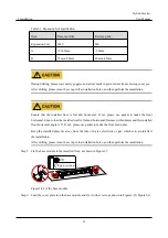
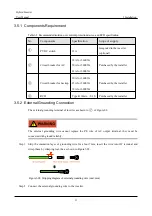
Step 1 Strip the insulation layer of grounding wire for about 7mm, insert the wire into OT terminal and
crimp them by crimping tool, the as shown in Figure3-28.
Figure3-28 Stripping diagram of external grounding wire (unit: mm)
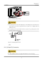
Step 2 Connect the external grounding wire to the inverter.

