MR33 Series (75K-600K) Modular UPS
User Manual
2 Overview
All rights reserved ©Kehua Hengsheng Co., Ltd.
17
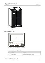
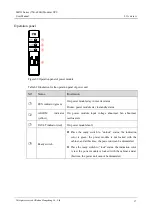
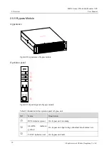
Operation panel
Figure2-9
Operation panel of power module
Table2-2
Illustration for the operation panel of power unit
NO.
Name
Illustration
○
1
RUN indicator (green)
On: power module stay in inverter status
Flicker: power module stay in standby status.
○
2
ALARM
indicator
(yellow)
On: power module input voltage abnormal, fan abnormal,
overload, etc.
○
3
FAULT indicator (red)
On: power module fault.
○
4
Ready switch
Place the ready switch to “unlock” status, the indication
color is green, the power module is not locked with the
cabinet, and at this time, the power unit can be dismantled.
Place the ready switch to “lock” status, the indication color
is red, the power module is locked with the cabinet, and at
this time, the power unit cannot be dismantled.
Summary of Contents for MR33 Series
Page 2: ...MR33 Series 75K 600K Modular UPS User Manual...
Page 3: ......
Page 11: ......
Page 123: ...4402 02833 004...


