MY-A Series (10kVA-20kVA) UPS
User Manual
5 LCD Screen Operation
77
5.2 Main Page
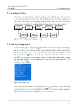
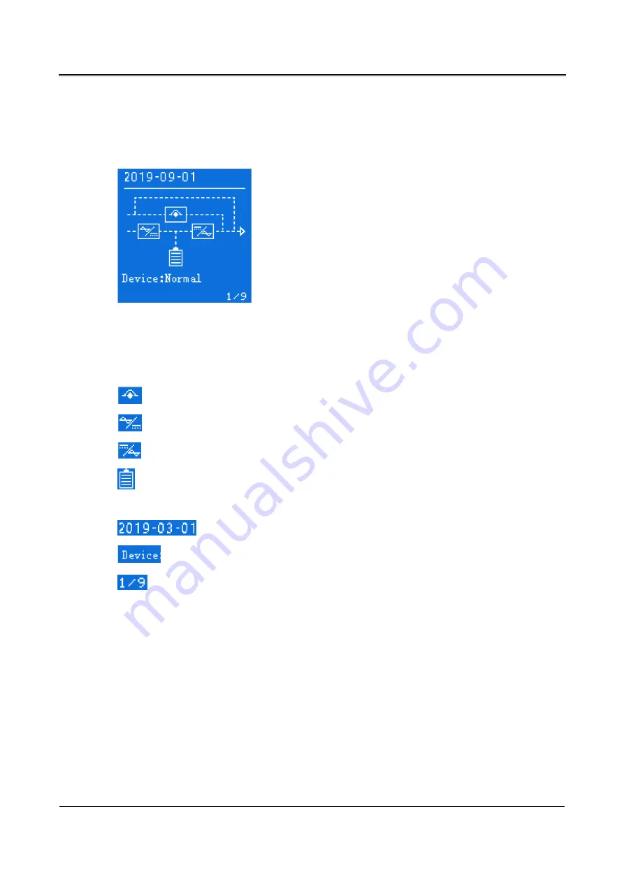
After the UPS is powered on, it will enter the system monitoring main interface, as shown in
Figure5-2, the interface default display energy flow chart.
Figure5-2
Main page
After entering the main interface, it is easy to monitor the system. The meaning of the icons on the
main interface is as follows:
: System bypass icon.
: System rectifier icon.
: System inverter icon.
: System battery icon. The internal energy bar of the battery changes accordingly depending on
the current battery status and battery voltage.
: System current date display.
: System current operating status display.
: Monitor page number display.
The working state and energy flow on the main interface visually describe the operating state of the
system.
5.3 System Working Status Display
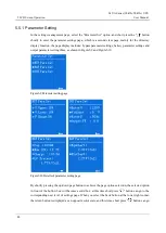
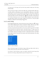
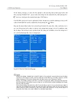
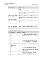
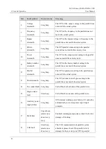
The operating status of the system have 4 modes: main power inverter output, battery inverter output,
ECO bypass output, maintenance bypass output. Interface display for each working status as shown


