background image

String PV Grid-tied Inverter SPI-B-H Series (175K-250K) 

User Manual 

2Overview 


All rights reserved ©Kehua Hengsheng Co., 

Ltd.


7


Inverter

Transformer

IT

PE

L1
L2

L3


Figure2-2


Grid mode 

2.1.1 Features 


Adopts the efficient three level high frequency conversion technology and advanced full digital 

control technology. 


Good power grid adaptability and excellent power quality. 


The reactive power is adjustable, the range of power factor is -0.8(lag)

+0.8(ahead). 


The active power can be adjusted form 0% to 100% continuously. 


Perfect protection functions: island protection, high/low voltage ride through, reverse DC 

connection protection, AC short circuit protection, leakage current protection, surge protection, 

etc. 

2.1.2 Model Meaning 

SPI 

□□□

K-B-H

Product series mark

SPI series PV grid-tied inverter.

Rated output power mark

When it is 175, that means the rated power of the UPS is 175kVA;
When it is 225, that means the rated power of the UPS is 225kVA;

And so on.

Voltage type mark

H

represents high-voltage.

Isolation type mark

B

represents non-isolated power.


Figure2-3


Model meaning 

Summary of Contents for SPI-B-H Series SPI175K-B-H

Page 1: ...String PV Grid tied Inverter SPI B H Series 175K 250K User Manual...

Page 2: ......

Page 3: ...e purchase scope or the usage scope Unless otherwise specification in the contract all statements information and recommendations in this document are provided AS IS without warranties guarantees or r...

Page 4: ...save the manual after reading in order to consult in the future The figures in this manual are just for reference for details please see the actual product Applicable Model SPI175K B H SPI200K B H SPI...

Page 5: ...formance deterioration or unanticipated results Anti static prompting Be care electric shock prompting Provides a tip that may help you solve a problem or save time Provides additional information to...

Page 6: ...g Requirements 4 1 1 5 Moistureproof Protection 4 1 1 6 Warning Mark Setting 4 1 1 7 Electrical Connection 4 1 1 8 Measurement Under Operation 5 1 2 Operator Requirements 5 2 Overview 6 2 1 Product In...

Page 7: ...allation carrier requirements 20 3 4 Handling Unpacking and Checking 21 3 4 1 Handling 21 3 4 2 Unpacking and Checking 23 3 5 Inverter Installation 23 3 5 1 Bracket installation 23 3 5 2 Wall mounting...

Page 8: ...vi All rights reserved Kehua Hengsheng Co Ltd 5 Maintenance and Troubleshooting 48 5 1 Maintenance 48 5 2 Troubleshooting 49 6 Package Transportation Storage 52 6 1 Package 52 6 2 Transportation 52 6...

Page 9: ...scribes the safety announcements when operation and maintenance For details please refer to safety description in the relevant chapters Before operation please read the announcements and operation ins...

Page 10: ...he device please check whether there is no damage or danger in the device visually Check whether the connection for other external devices or circuits is safe After disconnect the input and output of...

Page 11: ...PV array by light proof material or the PV array will generate high voltage under sunshine If touching PV array accidently it may cause electric shock or human injury There exists dangerous voltage b...

Page 12: ...ter damage Observe the following items to ensure that inverter works normally When the air humidity is more than 95 don t open the door of inverter In the wet or damp weather don t open the door of in...

Page 13: ...ement under operation it must take protection measure such as wear insulated gloves etc The measuring device must meet the following requirements The range and operation requirements of measuring devi...

Page 14: ...then feedbacks to power grid which is suitable for the large power station grid tied system The PV grid tiedgeneration system consists of PV array PV grid tied inverter transformer According to practi...

Page 15: ...0 8 lag 0 8 ahead The active power can be adjusted form 0 to 100 continuously Perfect protection functions island protection high low voltage ride through reverse DC connection protection AC short cir...

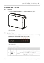
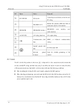
Page 16: ...Appearance 2 2 2 Operation Panel There are 4 status indicators on the front panel of the inverter which can indicate the current working status of the inverter The status of each indicator is shown in...

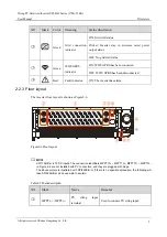
Page 17: ...disconnected 4 Red Fault indicator ON The inverter has alarm 2 2 3 Floor layout The inverter floor layout is shown as Figure2 6 Figure2 6 Floor layout SPI175K B H is 18 DC inputs The connection ident...

Page 18: ...8 Internal ground inlet hole For internal ground 9 External ground terminal Used for reliable grounding of the inverter DC Switch The DC switch the position is shown as 2 in Figure2 6 is the connectio...

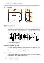
Page 19: ...lized through the inverter circuit As shown in 0 Output EMI filtering Relays PV24 C HCT HCT HCT PV2 PV1 C PV23 PWM GND MPPT1 MPPT12 L1 L2 L3 PE Input EMI filtering SPD GND GND DC switch L1 L2 L3 Figur...

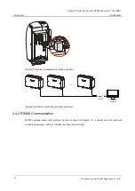
Page 20: ...9 Ethernet communication interface location Inverter Monitoring platform Inverter Inverter Router Figure2 10 Ethernet monitoring multiple inverters 2 4 2 RS485 Communication RS485 communication the i...

Page 21: ...verter 1 N 20 Figure2 12 RS485 communication multi unit inverters When only one inverter communicates via RS485 choose one of the two communication interfaces to connect 2 4 3 WIFI GPRS Communication...

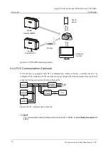
Page 22: ...l If the inverter is equipped with PLC communication Kehua sub array controller needs to be configured The output end of the machine must pass through the isolation transformer and then be connected t...

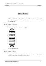
Page 23: ...n procedures electrical connection check the installation etc 3 1 Installation Process The installation process of inverter is as shown in Figure3 1 Start Electrical connection Check the installation...

Page 24: ...3Installation String PV Grid tied Inverter SPI B H Series 175K 250K User Manual 16 All rights reserved Kehua Hengsheng Co Ltd Tools...

Page 25: ...on the service life and reliability of the equipment Therefore please pay attention to avoid using the equipment in the following working environment Do not install the inverter in high or low temper...

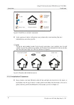
Page 26: ...ich plays a very important role in its safe operation service life performance guarantee etc Therefore it is recommended to choose a location that can avoid direct sunlight rain and snow As shown in F...

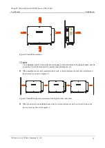
Page 27: ...of the indicator lights and it is convenient for electrical connection operation and maintenance etc When multiple inverters are installed side by side a certain distance must be reserved between the...

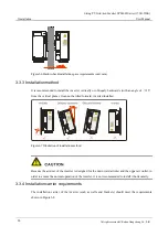
Page 28: ...an angle of 15 from the vertical plane It cannot be tilted forward inverted installed Figure3 7 Illustration of installation method Because the air duct of the inverter is designed for the downward a...

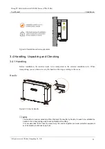
Page 29: ...ransported to the selected installation site When transporting you can choose to carry the handle or the ring according to the scene Handle Figure3 9 Curry by handle The handle is a random accessory W...

Page 30: ...nals of the case or bottom and it is necessary to lay protective materials such as sponge pads or foam underneath it Ring transport Figure3 10 Ring transport The hoist ring is an optional accessory Wh...

Page 31: ...e for shipping damage if any shipping damage is found report it to the carrier immediately Check if the types of the accessories are complete and correct If there is any discrepancy take notes and con...

Page 32: ...t as shown in Figure3 12 Please ensure that the wall mount is level to ensure that the mounting holes are consistent and aligned Figure3 12 Mark the mounting holes position You can also directly mark...

Page 33: ...40 bolts put on flat washers spring washers and nuts and then tighten the nuts clockwise with a wrench to fix the wall mount to the bracket as shown in Figure3 15 Figure3 15 Fix the wall mount on the...

Page 34: ...Hengsheng Co Ltd Figure3 16 Hang the inverter on the wall bracket After confirming that the inverter is fixed firmly the operator can release the equipment Step 6 Use the screws M5 50 in the accessori...

Page 35: ...ll mount assembly through the connecting rod as shown in Figure3 18 Figure3 18 Assembling the wall mount Step 2 Place the assembled wall mount at the installation point use a spirit level to adjust th...

Page 36: ...ing hole size unit mm Step 3 According to the marked position use a hammer drill to drill holes in the wall Punching hole size is 14 5mm depth range is 55 60mm Figure3 21 Punching holes After drilling...

Page 37: ...ount to the expansion bolts cover with flat washers spring washers and nuts and then tighten the nuts clockwise with a wrench to fix the wall mount to the wall as shown in Figure3 23 Figure3 23 Fix th...

Page 38: ...Hengsheng Co Ltd Figure3 24 Hang the inverter on the wall bracket After confirming that the inverter is fixed firmly the operator can release the equipment Step 7 Use the screws M5 50 in the accessori...

Page 39: ...process may cause equipment damage or personal injury Wiring operation must be completed only by professional technicians The cables used in the PV power generation system must be firmly connected in...

Page 40: ...lded twisted pair 2 0 3 mm2 Maximum outer diameter 14mm External ground wire Outdoor cable Conductor cross sectional area S 2 S is the AC output wire conductor cross sectional area 1 The cables in thi...

Page 41: ...on of the external ground terminal cannot replace the connection of the internal ground terminal Make sure that both are grounded reliably otherwise Kehua will not bear any responsibility for possible...

Page 42: ...ection after the bottom line is installed The grounding of the inverter and the lightning rod of the inverter installation building cannot be the same the two need to be separated as shown inFigure3 2...

Page 43: ...ing to the total current No load can be connected between the inverter and the circuit breaker Terminal requirements When the AC output uses copper wire it is recommended to use DT OT terminals as sho...

Page 44: ...door panel of the wiring box After the door panel is opened the limit rod needs to be fixed as shown in Figure Figure3 31 to facilitate the wiring operation Figure3 31 Schematic diagram of limit rod...

Page 45: ...and then connect to the AC output terminal block as shown in Figure3 32 Figure3 32 Connect the AC output cable The torque used when tightening the externally forced cable fixing head of AC wiring is...

Page 46: ...le machines are connected in parallel the back end of the AC output of the inverter needs to be equipped with a circuit breaker with an impact tripping function or an open circuit Step 3 Tighten the e...

Page 47: ...Co Ltd 39 Figure3 34 Connect internal ground The torque used when tightening the externally forced cable fixing head of the internal ground wire is about 10 13N m 3 6 6 PV string input wiring Pay att...

Page 48: ...f accidentally lost or damaged you need to purchase the same type of photovoltaic connector Equipment damage caused by the use of incompatible models of photovoltaic connectors is not covered by the e...

Page 49: ...ative connectors pass the positive and negative cables through the corresponding lock nuts and use a crimping tool to press the positive and negative metal terminals respect to the positive cable and...

Page 50: ...ate Figure3 39 Schematic diagram of DC switch OFF state Step 2 Check whether the polarity of the connection cable of the PV string is correct and ensure that the open circuit voltage in any case does...

Page 51: ...tick insert the equipped WIFI GPRS stick into the WIFI GPRS port to do the internet monitoring as shown in Figure3 42 Figure3 42 WIFI GPRS communication connection When connecting pay attention to the...

Page 52: ...re Ethernet communication connection Crimp the Ethernet communication cable according to 0 and then plug it into the Ethernet communication interface on the communication board as shown in Figure3 43...

Page 53: ...S485 communication wire must be routed separately from the input and output wires to avoid interference with communication The baud rate of the inverter needs to be set through the Kehua monitoring so...

Page 54: ...must be switched to the ON position The communication address of the inverter must not conflict Step 3 After connecting the cable tighten the external forced cable fixing head seal with fireproof mud...

Page 55: ...ter and grid the fault indicator is off Step 3 If the DC and AC supply power normally the inverter will prepare to start Step 4 A moment later the inverter will generate power normally The grid connec...

Page 56: ...dissipation performance of the inverter and can be cleaned with a soft brush If the surface of the LED indicator is too dirty to read you can clean it with a damp cloth The external cooling fan is aea...

Page 57: ...e inverter may stop power generation The fault situation is as shown in Table5 1 Table5 1 Fault situation NO Fault information Deal way 1 Abnormal grid voltage Check whether the safety regulations of...

Page 58: ...your local agency or service center 9 Fan abnormal If the fault persists please contact your local agency or service center 10 Over temperature of cabinet inside Check whether the radiator of the inve...

Page 59: ...n inverter refer to 4 2 Shut Down Inverter 5 minutes later restart the inverter refer to 4 1 Start Inverter If the alarm status is not removed please contact our local agency or service center Before...

Page 60: ...ith the objects that inflammable explosive or corrosive Don t put device in the open air warehouse when transshipment Leaching and mechanical damage by rain snow or liquid objects is prohibited 6 3 St...

Page 61: ...h full load Vdc 860 1300 PV connected MPPT tracking 18 9 DC current of each route A 0 9 15 PV input power kW 0 175 193 Startup voltage V 550 Grid features Output power kW 175 193 Rated grid voltage Va...

Page 62: ...P66 Isolation type No isolation With no transformer the input cannot be connected with ground or the grounding output must be with isolation transformer Heat dissipation way Smart wind cooling Noise 7...

Page 63: ...0 9 15 PV input power kW 0 220 220 Startup voltage V 550 Grid features Output power kW 200 220 Rated grid voltage Vac 800V 3P3W Grid voltage range Vac 720 800 880 Settable If it is necessary to set th...

Page 64: ...n transformer Heat dissipation way Smart wind cooling Noise 75 2dBA 1m Do not install in a noise sensitive environment Display way LED indicator Communication port RS485 Ethernet WIFI optional GPRS op...

Page 65: ...Vac 800V 3P3W Grid voltage range Vac 720 800 880 Settable If it is necessary to set the parameter please contact the manufacturer Frequency range Hz 48 50 50 5 Settable If it is necessary to set the...

Page 66: ...onment Display way LED indicator Communication port RS485 Ethernet WIFI optional GPRS optional PLC optional Operation temperature 35 25 60 Storage temperature 40 25 70 Relative humidity 0 100 Atmosphe...

Page 67: ...he manufacturer Frequency range Hz 48 50 50 5 Settable If it is necessary to set the parameter please contact the manufacturer Grid tied inverting efficiency 99 0 Grid tied China efficiency 98 4 Grid...

Page 68: ...ation Display way LED indicator Communication port RS485 Ethernet WIFI optional GPRS optional PLC optional Operation temperature 35 25 60 Storage temperature 40 25 70 Relative humidity 0 100 Atmospher...

Page 69: ...ms and Abbreviations All rights reserved Kehua Hengsheng Co Ltd 61 B Acronyms and Abbreviations A AC Alternating Current D DC Direct Current L LCD Liquid Crystal Display LED Light emitting Diode M MPP...

Page 70: ...B Acronyms and Abbreviations String PV Grid tied Inverter SPI B H Series 175K 250K User Manual 62 All rights reserved Kehua Hengsheng Co Ltd RS485 Recommend Standard485...

Page 71: ...4402 00000001...
Reviews: