PV Grid-tied Inverter SPI-B X2 Series (8K-25K)
User Manual
2 Overview
All rights reserved ©Xiamen Kehua Digital Energy
Tech Co., Ltd.
9
2.2.2 External Terminal Illustration
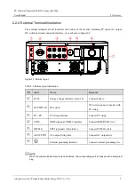
The external terminals are all located at the bottom of the inverter, including PV input, AC output,
DC switch and communication interface, etc. as shown in Figure2-5.
Figure2-5
Bottom layout
Table2-2
Bottom layout illustration
NO. Mark
Name
Remarks
○
1
B+/B-
Energy storage interface (reserved)
Connect battery.
○
2
DC SWITCH
DC switch
DC switch connects inverter with
PV string.
○
3
PV+/PV-
PV string terminal
Connect PV string.
○
4
COM.
DRM (optional) /RS485 interface
Connect DRM/RS485 wire.
○
5
WIFI/4G
WIFI (optional) /4G interface
Connect WIFI/4G stick.
○
6
AC OUTPUT
AC output wiring hole
Connect AC output wire.
○
7
External grounding terminal
Connect external grounding wire.
When the communication function is not selected, the corresponding port is blocked with a waterproof
plug.
Summary of Contents for SPI-B X2 Series
Page 1: ...PV Grid tied Inverter SPI B X2 Series 8K 25K User Manual...
Page 2: ......
Page 58: ...4402 04048 002...

