background image

PV Grid-tied Inverter SPI-B X2 Series (8K-25K) 

User Manual 

3 Installation 


All rights reserved ©Xiamen Kehua Digital Energy 

Tech Co., Ltd.


31


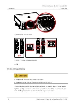
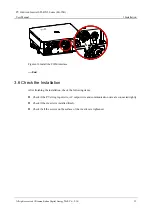
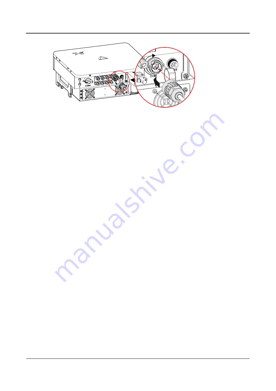
Figure3-32


Install the COM. interface 

----End 

3.6 Check the Installation 

After finishing the installation, check the following items: 


Check if the PV string input wire, AC output wire and communication wire are connected rightly. 


Check if the inverter is installed firmly. 


Check if all the screws on the surface of the inverter are tightened. 

Summary of Contents for SPI-B X2 Series

Page 1: ...PV Grid tied Inverter SPI B X2 Series 8K 25K User Manual...

Page 2: ......

Page 3: ...he products services and features described in this document may not be within the purchase scope or the usage scope Unless otherwise specification in the contract all statements information and recom...

Page 4: ...lectrical connection operation maintenance and storage etc Please save the manual after reading in order to consult in the future The figures in this manual are just for reference for details please s...

Page 5: ...y or death Alerts you to a medium low risk hazard that could if not avoided result in moderate or minor injury Alerts you to a low risk hazard that could if not avoided result in minor injury Anti sta...

Page 6: ...3 1 1 5 Moistureproof Protection 3 1 1 6 Warning Mark Setting 4 1 1 7 Electrical Connection 4 1 1 8 Measurement Under Operation 4 1 2 Operator Requirements 5 1 3 Operation Environment Requirements 5...

Page 7: ...External Grounding Connection 19 3 5 3 PV String Input Wiring 21 3 5 4 AC Output Wiring 24 3 5 5 WIFI 4G Communication Connection 27 3 5 6 COM Communication Connection Optional 28 3 6 Check the Insta...

Page 8: ...Inverter SPI B X2 Series 8K 25K User Manual vi All rights reserved Xiamen Kehua Digital Energy Tech Co Ltd 7 1 Package 41 7 2 Transportation 41 7 3 Storage 41 A Technical Specifications 42 B Acronyms...

Page 9: ...ents when operation and maintenance For details please refer to safety description in relevant chapters Before operation please read the announcements and operation instructions in this section carefu...

Page 10: ...til all power sources are switched off for 20 minutes and check that there is no voltage and current in the inverter by the detection equipment The surface temperature of the inverter may reach to 75...

Page 11: ...ic wrist strap before touching sensitive components and the other end is well grounded 1 1 4 Grounding Requirements High leakage risk The inverter must be grounded before wiring The grounding terminal...

Page 12: ...Electrical connection must be performed according to the description in the user manual and the electrical schematic diagram The configuration of PV string grid level grid frequency etc must meet the...

Page 13: ...the related standards of local country and district 1 3 Operation Environment Requirements Avoid the inverter suffering directly sunshine rain or snow to prolong the service life detail please see 3...

Page 14: ...s suitable for the commercial roof grid tied system and large power station grid tied system The PV grid tied generation system consists of PV string PV grid tied inverter and grid as shown in Figure2...

Page 15: ...eatures Efficiently power generation adopt high efficiency type T three level high frequency conversion technology and advanced completely digitized control technology wide work range of MPPT and high...

Page 16: ...dicator The LED indicator on the front panel of inverter shows the inverter status as shown in Table2 1 Table2 1 LED indicator status illustration Indicator Status Meaning Green indicator is on Invert...

Page 17: ...2 2 Bottom layout illustration NO Mark Name Remarks 1 B B Energy storage interface reserved Connect battery 2 DC SWITCH DC switch DC switch connects inverter with PV string 3 PV PV PV string terminal...

Page 18: ...maintenance or wiring the DC switch must be disconnected 2 3 Working Principle PV strings are connected to inverter and do the max power point tracking for PV strings through the two groups of MPPT ci...

Page 19: ...r s installation including installation process installation preparation transportation and unpacking installation procedures electrical connection check the installation etc 3 1 Installation Process...

Page 20: ...Co Ltd Tools The installation tools need to be insulated to avoid electric shock 3 2 2 Installation Environment Do not install the inverter in the place with poor ventilation Ensure that there has suf...

Page 21: ...n Figure3 2 The installation height of the inverter should be convenient for viewing the indicator status Figure3 2 Recommended installation site 3 2 3 Installation Clearance Keep a clearance of at le...

Page 22: ...inverter vertically do not put it down or put it up suddenly 3 3 2 Unpacking and Checking Select the unpacking site in advance In principle the unpacking site should be as close to the installation si...

Page 23: ...nd Hazardous Substances Product Quality Inspection Report Business License Solar Energy Certification If the inverter needs to be stored for a long time after unpacking it is necessary to pack the inv...

Page 24: ...3 6 Size unit mm Step 2 Mark the position of installation holes on the wall according to the dimensions of the fixing holes of the installation holder as shown in Figure3 7 and drill three holes of 10...

Page 25: ...be within 40mm Clear the dust and measure the net depth Ensure that the depth of three holes is the same Step 3 Install the equipped three expansion bolts M6 60 into the holes as shown in Figure3 9 Fi...

Page 26: ...to the installation holder as shown in Figure3 11 Do not loosen the inverter until the inverter has been hung in the installation holder completely Figure3 11 Hang the inverter to installation holder...

Page 27: ...above multi core wire SPI23K B X2 SPI25K B X2 SPI25K B X2P Note the outer diameter of multi core wire should be less than 25mm COM communication wire 8 core network wire Grounding wire 4 mm2 6 mm2 The...

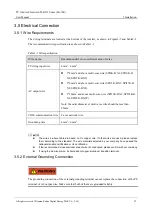
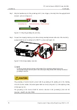
Page 28: ...steel combination bolt M5 12 as shown in Figure3 14 Figure3 14 External grounding connection In order to improve the anti corrosion performance of the external grounding terminal it is recommended to...

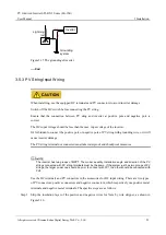
Page 29: ...f PV string with grounding wire or it will cause inverter damage The PV string terminal not connected must take waterproof and shockproof measures The inverter has two groups of MPPT The model quantit...

Page 30: ...negative connectors draw the positive and negative wires through the corresponding lock nuts and crimp the positive wire and negative wire to the positive and negative metal terminals respectively and...

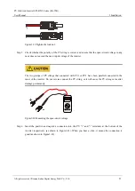
Page 31: ...ut voltage of the inverter The two groups of PV strings that connected with PV1 or PV2 have been parallel connected in the inner of the inverter Do not reverse connect the PV string or it will cause t...

Page 32: ...AC Output Wiring It s forbidden that several inverters share an AC switch It s forbidden to connect with load between inverter and the AC switch To ensure the inverter can be disconnected with load s...

Page 33: ...sh the AC live wire neutral wire and grounding wire Step 1 Strip the external insulation layer of AC wire for about 70mm strip the inner lead insulation layer for about 15mm as shown in Figure3 23 Fig...

Page 34: ...rminal by screwdriver as shown in Figure3 24 Figure3 24 Connect the AC output wire Step 3 After wiring fasten the AC output waterproof cover to the inverter by equipped four stainless steel combinatio...

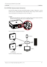
Page 35: ...unning information through WiseSolar APP or Energy Cloud to realize the internet monitoring the monitoring scheme is as shown in Figure3 27 When installing the WIF 4G stick pay attention to the limiti...

Page 36: ...market Android Chinese user 2 APP store iOS Method 2 scan the QR code below to download and install the WiseSolar APP according to prompting End 3 5 6 COM Communication Connection Optional COM interf...

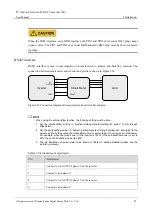
Page 37: ...rt meter and inverter and grid When using the anti backflow function the following setting must be done 1 Set the anti backflow setting in System Setting General Setting I O switch to ON through WiseS...

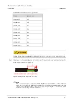
Page 38: ...on procedure The connection of COM interface is as follows Step 1 Strip the insulation layer of communication wire by wire stripper loosen the lock nut of waterproof RJ45 connector and then draw the c...

Page 39: ...1 Figure3 32 Install the COM interface End 3 6 Check the Installation After finishing the installation check the following items Check if the PV string input wire AC output wire and communication wire...

Page 40: ...fastened and the insulation layer of wires are good Ensure the gap between the nylon cable gland and wires and the unconnected connectors are sealed well Ensure that the grid voltage meets the AC vol...

Page 41: ...power are all normal the inverter will prepare to start grid tied Check the inverter parameters and the grid parameters if they are in the normal range a moment later the inverter will perform the ins...

Page 42: ...erter needn t to be maintained regularly but the sundries or dust may influence the heat dissipation performance so use soft brush to clean the inverter If the LED indicator surface is too dirty to re...

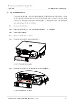
Page 43: ...d or cause derating Therefore it is necessary to keep the fan clean and replace the damaged fan in time The cleaning and replacement steps of the fan are as follows Step 1 Disconnect the AC switch Ste...

Page 44: ...is of the grid tied operation standards and meets the requirements of safety and EMC Before provided to client the inverter has been experienced for several rigorous tests to ensure reliable and optim...

Page 45: ...r of the inverter is blocked and check whether the ambient temperature of the inverter is too high or too low If the above is normal and the fault still exists please contact your local agency or serv...

Page 46: ...or service center 15 Inner abnormal If the fault exists please contact your local agency or service center If the inverter has an alarm mentioned in Table5 1 please shut down inverter refer to 4 3 Sh...

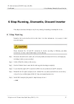
Page 47: ...llowing procedures successively or it may cause human injury or device damage Step 1 Disconnect the external AC switch and set warning marks at disconnected site to avoid improperly switching on and e...

Page 48: ...antled Step 1 Disconnect all connection successively in reversed procedures of 3 5 Electrical Connection Step 2 Dismantle the inverter in reversed procedures of 3 4 Inverter Installation Step 3 If the...

Page 49: ...ice with the objects that inflammable explosive or corrosive Don t put device in the open air warehouse when transshipment Leaching and mechanical damage by rain snow or liquid objects is prohibited 7...

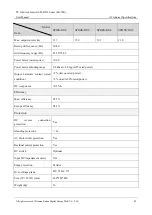
Page 50: ...ut power kW 10 8 13 5 16 2 20 3 Max input voltage V 1100 MPPT voltage range V 180 1000 MPPT voltage with full load V 300 850 350 850 400 850 350 850 Startup voltage V 150 No of MPPTs 2 Strings per MPP...

Page 51: ...tor rated power 0 99 Power factor adjusting range 0 8 ahead 0 8 lag 0 8 rated power Output harmonic content rated condition 3 test on rated power 5 load is 50 rated power DC component 0 5 In Efficienc...

Page 52: ...e humidity 0 100 without condensation Cooling method Natural cooling Smart cooling Operating altitude 4000m 3000m derating Noise 30dB 1m 50dB 1m Display LED Communication method RS485 WIFI optional 4G...

Page 53: ...rent A 45 30 15 60 30 30 60 30 30 60 30 30 60 20 40 AC output Rated output power kW 17 20 23 25 25 Max output power kW kVA 18 7 22 25 3 27 5 Rated grid voltage Vac 400 Grid voltage range V 320 480 Gri...

Page 54: ...s AC short circuit protection Yes Residual current protection Yes DC switch Optional Input DC impedance monitor Yes Surge protection Varistor Over voltage grade DC AC Size W D H mm 460 182 420 Weight...

Page 55: ...ch Co Ltd 47 Model Item SPI17K B X2 SPI20K B X2 SPI23K B X2 SPI25K B X2 SPI25K B X2P Communication method RS485 WIFI optional 4G smart meter optional anti backflow optional AC terminal Wiring terminal...

Page 56: ...Manual 48 All rights reserved Xiamen Kehua Digital Energy Tech Co Ltd B Acronyms and Abbreviations A AC Alternating Current D DC Direct Current L LCD Liquid Crystal Display LED Light emitting Diode M...

Page 57: ...PV Grid tied Inverter SPI B X2 Series 8K 25K User Manual B Acronyms and Abbreviations All rights reserved Xiamen Kehua Digital Energy Tech Co Ltd 49 RS485 Recommend Standard485...

Page 58: ...4402 04048 002...

Reviews: