T-GPS User Manual Version 1.2 | 13
4.4
IRIG-B Signal Input Module
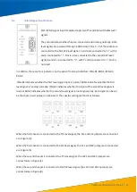
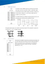
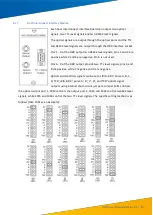
Each IRIG-B signal input module accepts two TTL and 422 switchable level
signals.
They can indicate whether they are connected and running normally. Both
level signals are accessed through a DB9 socket. Pins 1 - 4 of the socket are
connected to the first 422 level signal, 1 and 4 are connected to "+" with 2
and 3 connected to "-". Pins 6 -9 are connected to the second 422 level
signal, 6 and 9 are connected to "+", with 7 and 8 connected to "-".Pin 5 is
not used.
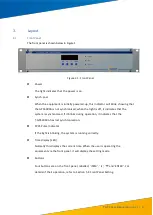
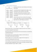
In addition, there are four indicators on the panel, from top to bottom: IRIG-B1, RUN1, IRIG-B2,
RUN2.
IRIG-B1 indicates whether the first level signal input is normal. RUN1 indicates whether the first
level signal is running normally. IRIG-B2 indicates whether the input of the second level signal is
normal. RUN2 indicates whether the second level signal is running normally. Each signal can be set
by the short circuit jumper on the board. The specific setting method is as follows:
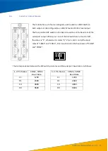
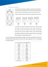
When the first channel is connected to the TTL level signal, the 1S1 and 1S2 jumpers are connected
as in Figure (a).
When the first channel is connected to the 422 level signal, the 1S1 and 1S2 jumpers are connected
as in Figure (b)
When the second channel is connected to a TTL level signal, the 1S21 and 1S22 jumpers are
connected as in Figure (c).
When the second channel is connected to the 422 level signal, the 1S21 and 1S22 jumpers are
connected as in Figure (d)


