T-GPS User Manual Version 1.2 | 14
4.5
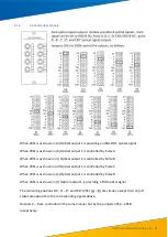
Dry Contact Pulse Output
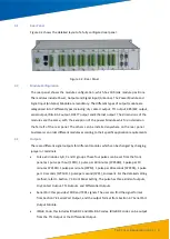
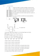
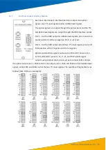
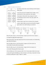
Maximum twelve inputs. Two connectors make a pair and are marked
with ‘c’ and ‘e’ from the top. The left column comprises numbers. 1, 3,
5, 7, 9, 11 and the right one is 2, 4, 6, 8, 10, 12 from top to bottom.
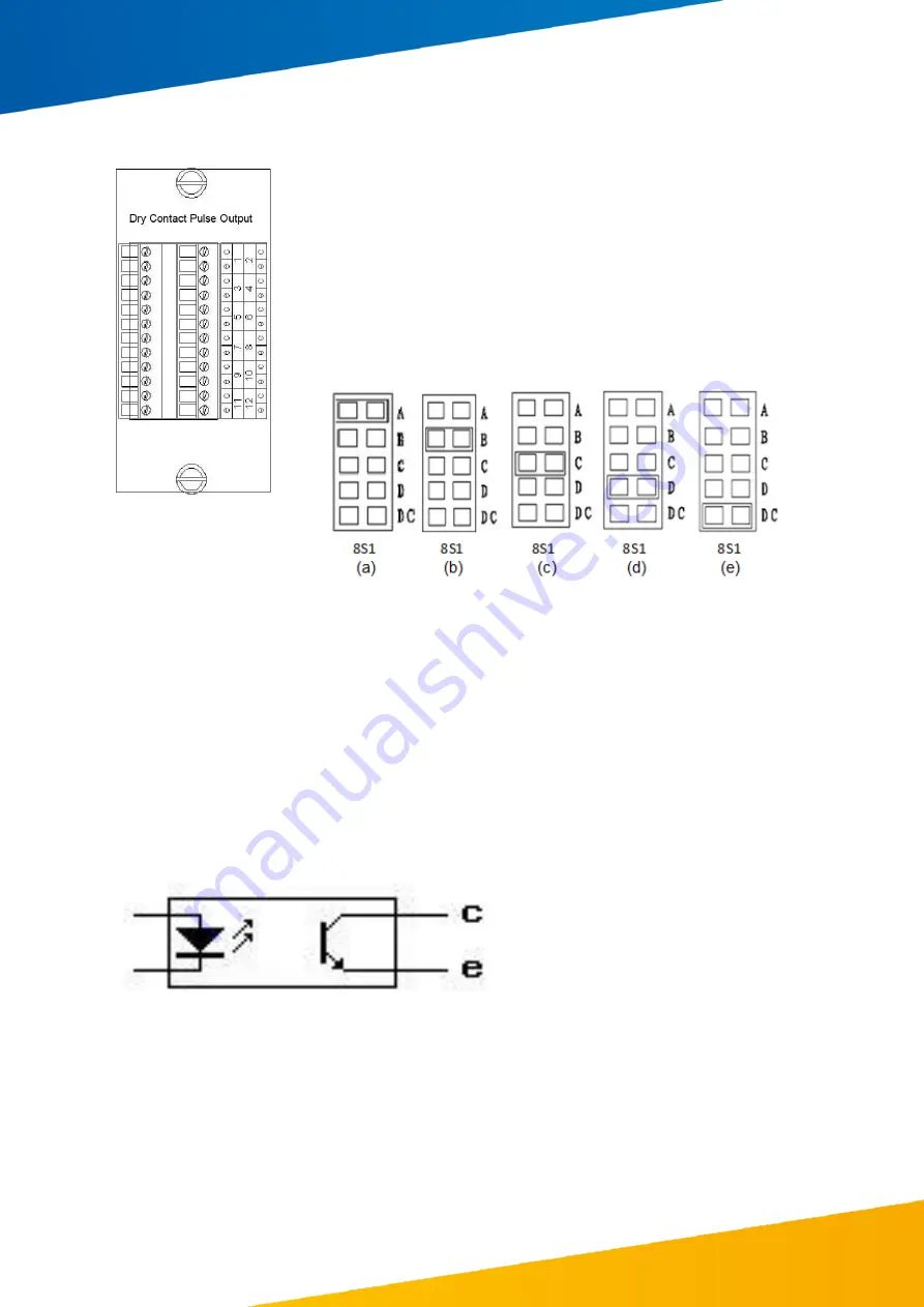
Each output can be set as an A, B, C or D pulse via the jumper on the
PCB. The 8S1 to 8S12 represents outputs 1 to 12.
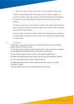
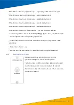
The detailed setting method is as following:
If 8S1 is in location (a), its output pulse is set to A.
If 8S1 is in location (b), its output pulse is set to B.
If 8S1 is in location (c), its output pulse is set to C.
If 8S1 is in location (d), its output pulse is set to D.
If 8S1 is in location (e), its output pulse outputs the IRIG-B DC signal.
The remaining 11 pairs have the same setting method. Below is the schematic fo r a dry contact.


