T-GPS User Manual Version 1.2 | 17
4.8
TTL Output Module
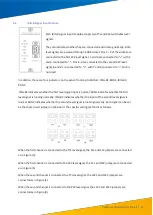
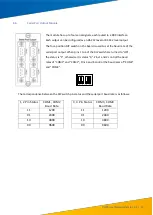
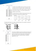
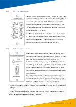
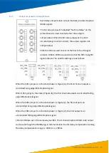
A maximum of twelve TTL outputs are provided in each module, each
output can be set to be either a Pulse or an IRIG-B output. The terminals
are in pairs with the upper one being
+
and lower one
-
. The left column
is marked 1, 2, 3, 4, 5 and 6; the right column is marked 7, 8, 9, 10, 11
and 12. Each signal can be set with a jumper as pulse A, B, C; pulse A’, B’,
C’ or IRIG
-B DC.
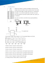
A’, B’ and C’ are similar to A, B, and C but have opposite polarities as
shown below
A, B, C
A’, B’, C’
TTL output format
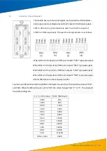
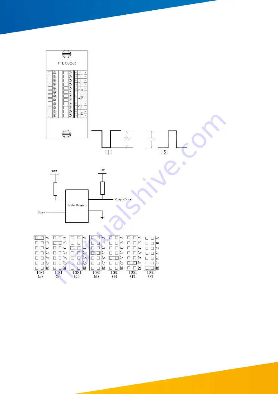
Jumper 10S1 to 10S12 controls outputs 1 to 12, the detailed settings are as follows:
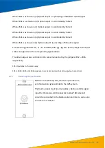
If 10S1 is as shown in (a), pair 1 outputs pulse A.
If 10S1 is as shown in (b), pair 1 outputs pulse B.
If 10S1 is as shown in (c), pair 1 outputs pulse C.
If 10S1 is as shown in (d), pair 1 outputs pulse A’, with opposite signal polarity
If 10S1 is as shown in (e), pair 1 outputs pulse B’, with opposite s
ignal polarity
If 10S1 is as shown in (f), pair 1 outputs pulse C’, with opposite signal polarity
If 10S1 is as shown in (g), pair 1 outputs an IRIG-B DC signal.
The setting method for 10S2 to 10S12 is the same as 10S1.


