T-GPS User Manual Version 1.2 | 22
4.17
Host Interconnect Interface Module
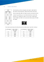
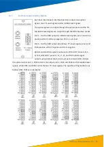
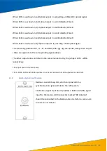
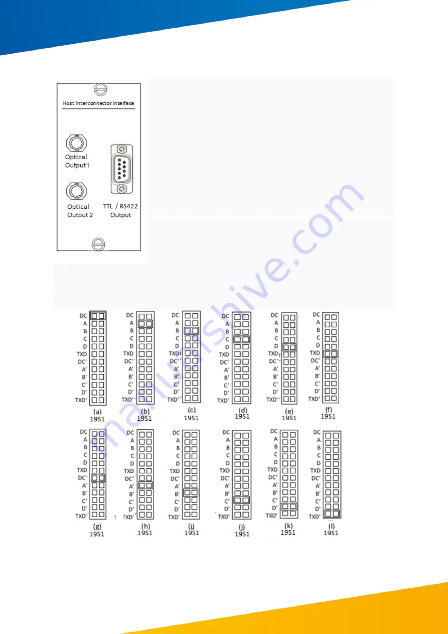
Each host interconnect interface board can output two optical
signals, two TTL level signals and two RS422 level signals.
The optical signals are output through the optical ports and the TTL
and RS422 level signals are output through the DB9 interface socket.
Pins 1 - 4 of the DB9 output two RS422 level signals; pins 1 and 3 are
positive while 2 and 4 are negative. Pin 5 is not used.
Pins 6 - 9 of the DB9 output provide two TTL level signals; pins 6 and
8 are positive while 7 negative and 9 are negative.
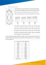
Optical and electrical signals can be set as IRIG-B DC; Pulse A, B, C,
D; TXD; IRIG-B
DC’
, pulse
A’
,
B’
,
C’
,
D’; a
nd
TXD’
optical signal
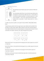
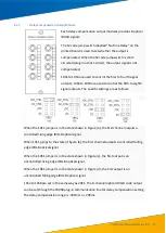
outputs using internal short-circuit jumpers. Jumper 19S1 controls
the optical output port 1, 19S2 controls the output port 2, 19S3 and 19S4 control two 422 level
signals, while 19S5 and 19S6 control the two TTL level signals. The specific setting method is as
follows (take 19S1 as an example):

