

10-5508 Rev A Service Department (800) 888-7009
6
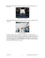
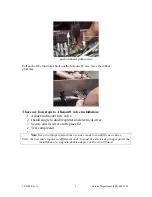
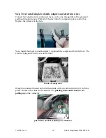
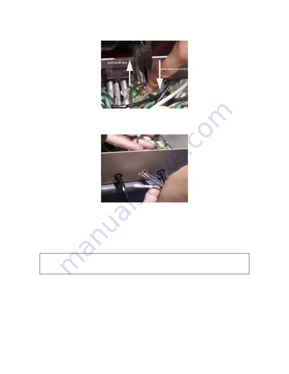
push on board, pull on wire
Pull each of the four wires back out the hole one by one. Save the rubber
grommet.
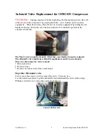
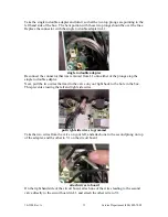
There are four steps to Allenair® valve installation:
1
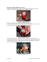
Adjust and mount new valve
2
Install single to double splitter and electrical wires
3
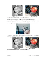
Secure and tie wires and replace lid
4
Test compressor
5
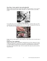
Note:
Keep two things in mind when you are ready to install the new valves
.
First, the new valve requires a different mount. Second, the electrical wiring requires the
installation of a single to double adapter on the circuit board.


