background image


27 

DOC06950  Rev. A

INSTALLATION / OPERATION & PARTS CATALOG 

CleenSweep

®

 - Manual (CSM)

24. Pull (unwind) all of the loose strap completely 

off of the winch, so the attachment screws 

are visible, and stretch it out past the end of 
the trailer, making sure that the strap is not 

twisted.  Cut the strap off, leaving enough 

strap to wrap around the top pipe 3 times. Drill 
(2) holes through the top pipe, equally spaced 
from the centerline of the pipe, and use the 

U-bolt to firmly attach strap to center of pipe. 

(See Tarp Assembly Instructions)

25. Retract the tarp as high as possible.  Trim the 

bottom of the tarp leaving 

12”-14” [305 - 356 

mm]

 laying on the floor.  Additional tarp on the 

floor (36”-48” [914-1219 mm]) may be needed 

if the material being unloaded is very light 
weight (low density).

26. Adjust wedge brake on winch. (See Winch 

Brake Adjustment)

Summary of Contents for CleenSweep Manual

Page 1: ...uarters Madras OR Toll Free 800 547 6161 Phone 1 541 475 3802 INSTALLATION OWNER S MANUAL PARTS CATALOG Original Instructions 2022 KEITH Manufacturing Co All Rights Reserved KEITH KEITH logo and WALKING FLOOR are registered trademarks of KEITH Manufacturing Co Equipment manufactured by KEITH Manufacturing Co is protected by numerous patents both domestic and foreign DOC06950 Rev A Released 2022 12...

Page 2: ...r Mounting Position Options 5 3 2 Winch Strap Roller Installation 6 3 2 1 Winch Installation Below Slope Shield 6 3 2 2 Strap Roller Assembly Installation Near Top of Front Wall 8 3 2 3 Strap Roller Assembly Installation Under Front Tarp Header 9 3 2 4 Option for High Density or High Flow Materials 10 3 3 Tarp Assembly Installation Adjustment 11 3 4 Tarp Modifications for Bullnose Trailer 15 3 5 T...

Page 3: ...ii DOC06950 Rev A INSTALLATION OPERATION PARTS CATALOG CleenSweep Manual CSM 9 0 Technical Support 38 10 0 Contact Information KEITH Manufacturing Co 38 11 0 Crank Handle Mounting Plate Template 39 ...

Page 4: ...he installers and operators read this entire manual before beginning the installation or operating of the system Please direct any questions to KEITH Manufacturing Co one of our international offices listed in the contact information section of this manual or on our website WARNING Always disconnect hydraulic and electric power to the trailer and follow lock out tag out safety procedures before en...

Page 5: ...G CO AND EXCLUDED FROM THIS WARRANTY FURTHER KEITH MANUFACTURING CO DOES NOT WARRANT THAT THE CLEENSWEEP TARP SYSTEM COMPLIES WITH LOCAL MUNICIPAL STATE OR FEDERAL CODES IF ANY AND THE BUYER ALONE IS RESPONSIBLE FOR ANY KNOWLEDGE OF ANY COMPLIANCE WITH ANY SUCH CODES This warranty shall not apply to any parts that a have been repaired or altered outside of the CleenSweep Tarp System b have been su...

Page 6: ...___________________________________________________________________ Address ________________________________________________________________________________ City State Prov _____________________________________________ Postal Code ________________ Country ________________________________________________________________________________ Phone _________________________________________________________...

Page 7: ... one should be in a full or filling trailer Lock out and tag out procedures must be followed before accessing the drive area 1 1 2 3 Safeguards must not be altered or bypassed 1 1 2 4 The user and system designer must understand the characteristics and safe handling requirements of the material that is being conveyed 1 1 2 5 Bulk materials are by nature unstable and flowable Avoid burial by avoidi...

Page 8: ...2 DOC06950 Rev A INSTALLATION OPERATION PARTS CATALOG CleenSweep Manual CSM 1 3 Marking of Machinery 1 3 1 Safety Decals KEITH Manufacturing Co www KeithWalkingFloor com Rev B ...

Page 9: ...ious injury Stay clear when in operation Lockout tagout before servicing KEITH CleenSweep Tarp System Remove handle when not in use and store in secure compartment when traveling Some or all of these safety decals may apply and be adhered to this system 2 0 Specifications 2 1 System Manual CleenSweep Dimensions 7 25 W x 10 5 H x 9 25 D 184 mm x 267 mm x 235 mm Weight 25 lbs 11 kg ...

Page 10: ...PERATION PARTS CATALOG CleenSweep Manual CSM 2 2 Component Identification Strap Roller Tarp Pipe Tarp Header Not shown Front Bulkhead Wall of Trailer Winch Assembly Front Slope Shield Floor Slats Tarp Assembly Removable Crank Handle ...

Page 11: ...trap Roller Mounting Position Options Guide Rails Skis short Tarp Header Strap Roller attached to tarp header Strap Roller attached to top of front wall Winch under slope shield H i g h F r o n t W a l l M o u n t C a p P l a t e M o u n t w i t h G u i d e R a i l s S k i s Winch under slope shield ...

Page 12: ...lation Winch mounted on front wall below front slope shield and strap roller mounted near top of front wall 3 2 1 Winch Installation Below Slope Shield NOTE Front wall of trailer may need to be reinforced to withstand the forces created by the winch 1 Locate and mark a centerline up the front wall of the trailer NOTE It is crucial that strap roller and the roll of strap on the winch is mounted in ...

Page 13: ... to mounting plate using the 4 M10 bolts B BOLT ATTACHMENT Transfer the winch mounting plate mounting bolt hole pattern to the wall and drill 2 17 32 13 mm bolt clearance holes Then attach the entire winch assembly to the trailer wall using 2 1 2 grade 8 M12 class 10 9 locking fasteners not included 3 Front shield modification It is recommended that the front shield be hinged or fitted with a door...

Page 14: ...nterline at the top of the front wall of the trailer 2 Measure down a minimum of 1 1 2 38 mm from the top to locate the strap roller mounting bracket 3 Center the strap roller bracket with the two mounting holes toward the top of the wall and weld in place or transfer the strap roller bracket bolt pattern to the wall and drill 3 7 16 11 mm bolt clearance holes 4 Attach the strap roller to the fron...

Page 15: ...the tarp to hang straight down and against the ski guide rails NOTE Front wall of the trailer and cap plate may need to be reinforced to withstand the forces created by the winch 1 Locate and mark the centerline of the cap plate 2 Locate the strap roller bracket far enough out from the front wall so that the tarp will hang straight down along the outside of the tarp guide rails when it is fully re...

Page 16: ...ION PARTS CATALOG CleenSweep Manual CSM 3 2 4 Option for High Density or High Flow Materials A High Sided Trailer with Sloped Cap Plate Prevents material from getting behind the tarp while loading and from getting stuck on top of cap plate ...

Page 17: ...Note If you are installing the tarp into a trailer with a V Floor system or into a bullnose trailer the tarp will need to be wider than the inside of the trailer because the tarp will conform to the ridges on the floor or the nose of the trailer See Tarp Modifications for V Floor Trailers for additional instructions If using Pipe in lower pockets C With the tarp laying down on the floor of the tra...

Page 18: ...nuts or rivets washers per UHMW strip installed from the bottom Handles on top of tarp Cut half the m aterial from each side equally Nylock Nuts Flat Washers Flanged Button Head Bolts OR Dome Head Bolts Large Flanged Dome Head Rivets Bolts or Rivets installed from the bottom so nothing sharp scrapes or catches on the floor Flanged Button Head or Dome Head Bolt Large Flanged Dome Head Blind Rivet 4...

Page 19: ...olt 4 Lay the tarp in the rear of the trailer with the handles on top of the tarp and the 2 50 mm top pipe resting inside of the trailer about 12 24 305 610 mm depending on type of material being unloaded making sure it is not past the ends of the slats when they are retracted to the front This will be where the tarp stops during unloading with the rest of the tarp hanging off the back of the trai...

Page 20: ... mm of tarp on the floor covering the slats Too much tarp on the floor and the tarp will get caught in the unloaded material and be difficult to remove Too little tarp on the floor and it won t move along with the load and sweep cleanly Additional tarp on the floor 36 48 914 1219 mm may be needed if the material being unloaded is very light weight low density M i n i m u m 1 2 1 4 3 0 5 3 5 6 m m ...

Page 21: ... the first pocket Short guide rails shown fabricated by installer Should be long enough to shield objects attached to front wall If using short guide rails shown the lower pockets must have UHMW strips that will flex into the bullnose of the trailer and be cut 2 50 mm shorter than the trailer wall width Follow Tarp Assembly Installation Adjustment Section 3 10 using UHMW strips for complete tarp i...

Page 22: ...rp should be approximately 6 152 mm wider than the inside of the trailer For a V 18 system the tarp should be approximately 7 178 mm wider A Start in the middle of floor and place weights or gravel dirt etc on the tarp between all the slats to hold the tarp down so it conforms to all of the slats B Cut both sides of the tarp equally along the trailer wall so that the tarp is now the same width as ...

Page 23: ...objects that will interfere with the operation of the tarp system If broom and shovel holders are installed and can t be remove guide rails skis will have to be installed to protect the tarp from catching or tearing 2 Measure the width of the trailer and mark the centerline on the front trailer wall with a permanent marker for future reference ...

Page 24: ...k on trailer 4 Measure 4 102 mm up from the top of the floor slats to locate the bottom of the mounting plate or place a spacer 1 25 mm thick at the bottom of the winch spool to keep winch placed at proper height 5 If trailer has an electrical box underneath the slope shield weld winch base plate to the exterior wall of the box ...

Page 25: ... without base on the inside wall of the trailer 7 Place winch base plate on exterior of front wall and bolt winch in place Note Extended fastening hardware NOT included 8 Use the handle mounting plate template inside the trailer included to ensure the bolts will be placed in an area that will not interfere with something inside the trailer when drilled from the exterior ...

Page 26: ...anual CSM 9 Mark appropriate measurement as reference on exterior of trailer 10 Use measurement from interior to place template in appropriate area Center punch all indicated areas to be drilled 11 Hole cut drill all necessary holes following sizes outlined on template ...

Page 27: ...achment Hardware NOT included 13 Fasten the handle assembly on the interior of the trailer with appropriate washers and lock nuts Note Attachment hardware NOT included 14 Connect drive shaft to both the handle assembly and winch assembly with supplied hardware Top up areas with grease by using the grease nipples attached and continue to do so on regular intervals ...

Page 28: ...the slope shield adjustments will need to be made to the slope shield A hole may need to be cut through the slope shield with a riser fabricated to create a gap over the spool and strap guides 16 See image of additional slope shield fabrication to compensate for a protruding winch assembly Be sure that the winch spool can rotate freely ...

Page 29: ...SM 17 If the winch assembly fits underneath the slope shield an opening must be cut into the front slope shield and a UHMW strap guide installed for the strap to pass through The opening must be centered along the path of the strap from the winch to the strap roller assembly ...

Page 30: ...OG CleenSweep Manual CSM 18 If trailer has broom shovel hooks on the front wall that can t be removed guide rails skis will need to be fabricated Guide rails skis keep the tarp from contacting the tool hooks preventing possible tarp tarp stiffener damage ...

Page 31: ...the tarp so the tarp fits between the side walls Excessive material will cause improper clean out 21 Trim the top 2 50 mm pipe 2 50 mm shorter than the width of the trailer and insert it in the top pocket Center the pipe in the pocket and rivet the tarp to the pipe fasteners not supplied 22 Trim the UHMW strips or something similar to the same length as the top pipe and insert them into the next t...

Page 32: ...mum clean out the tarp should be pulled further out of the trailer so that a minimum of 12 24 305 610 mm of the tarp remains in the trailer This will cause the tarp to pile up on the ground and potentially get caught up in the unloaded material if steps aren t taken to prevent this situation from occurring KEITH recommends that tarp hooks be installed to prevent the tarp from being buried under th...

Page 33: ...ap to wrap around the top pipe 3 times Drill 2 holes through the top pipe equally spaced from the centerline of the pipe and use the U bolt to firmly attach strap to center of pipe See Tarp Assembly Instructions 25 Retract the tarp as high as possible Trim the bottom of the tarp leaving 12 14 305 356 mm laying on the floor Additional tarp on the floor 36 48 914 1219 mm may be needed if the materia...

Page 34: ...28 DOC06950 Rev A INSTALLATION OPERATION PARTS CATALOG CleenSweep Manual CSM 27 Apply safety decals to trailer ...

Page 35: ...air of jam nuts is easiest to reach to turn the threaded rod to adjust the brake A deep socket on a ratchet works well to do this While turning the jam nut pair to turn the threaded rod it can help to put a finger on the wedge brake piece to make sure that the brake is traveling in the direction that you want it to if you can t easily see it Turn the threaded rod to tighten the brake against the s...

Page 36: ...he material is unloading 3 DO NOT let material build up on tarp It is recommended that the trailer be moved forward periodically during unloading and especially near the end of the unloading cycle move it 6 10 1830 3050 mm to reduce the amount of material unloaded on top of the tarp 4 After unloading the trailer make sure to stop the floor with all of the slats to the front of the trailer Dislodge...

Page 37: ...ver latch into the gear teeth attach the crank handle and manually crank in the tarp strap until the tarp is fully retracted to it s highest point and the U bolt is back up against the strap roller bracket 6 Ensure that the lever latch is fully engaged in the gear teeth and remove the crank handle and store in a safe location during travel ...

Page 38: ...railer after retracting Possible Cause Brake is not properly adjusted Solution See brake adjustment sections for instructions on how to properly adjust the brake Possible Cause Lever latch is not engaged in gear teeth Solution See operation sections for instructions on how to properly engage the lever latch Problem Tarp stops before fully retracting Possible Cause 1 Tarp is getting caught Solution...

Page 39: ...33 DOC06950 Rev A INSTALLATION OPERATION PARTS CATALOG CleenSweep Manual CSM 8 0 Parts Catalog Winch Assembly Serial number must be provided to determine actual part numbers 53 ...

Page 40: ...401 Socket Head Shoulder Screw ANSI B18 3 3M M8x1 25 x 43 25 18 1 87004570 BOLT HEX GR8 8 6MMx70MM 19 3 87009009 Hex Socket Button Head Cap Screw 20 3 96550552 Flat Washer 21 10310401 Brake Assembly 262mm All Thread Includes items 22 31 22 2 08418801 BRAKE HOLDING NUT FOR WINCH 08387701 23 1 08553901 ALL THREAD 10MM X 262MM CS 24 1 09095201 BRAKE 30 DEGREE ANGLE FOR CS WINCH 25 4 86651425 PIN ROLL...

Page 41: ...TING DYNALINE 378 1 4 28 THREAD 43 2 86562000 ND 60000436 WASHER FLAT 2 X1 ID 44 1 ND 70000027 E CLIP 1 45 1 86650260 ND 60000429 ROLL PIN 1 8 X5 8 46 1 86437520 ND 60000440 SHOULDER BOLT SOCKET HEAD 3 8 X1 47 2 86554001 BB ND FW838ZD WASHER FLAT 3 8 SAE 48 1 08247801 8247801 GEAR LOCK LEVER 3 8 STEEL PLATE KMD MINI WINCH 49 1 10769201 10769201 SPLINED SHAFT FOR MANUAL WINCH HANDLE 50 1 10769301 1...

Page 42: ...Includes items 1 5 6250302 STRAP ROLLER ASSEMBLY SS METRIC Includes items 1 5 1 1 06250401 STRAP ROLLER BRACKET UNVL CSH KSH AL 1 06250402 STRAP ROLLER BRACKET UNVL SS CSH UNIVERSAL MOUNT 2 1 1 05795501 STRAP ROLLER CSH 3 1 1 05813401 STRAP ROLLER BUSHING CSH 4 1 1 87013400 BOLT HEX 10 9 12MMX90MM 5 1 1 87102500 NUT HEX NYLOCK 12MM 1 75 ZINC 06250301 Universal Mount ...

Page 43: ...40150 3540150 UHMW STRIP FRONT SHIELD 96 1 4 X 2 7 8 W HOLES 3 1 ND 60000214 POLE 1 7 8 X 90 4 1 86671100 86671100 BOLT U SQ ASSY 5 16X2X3 11302 WASHER PLATE NUTS 5 1 ND 60000383 UHMW STRAP GUIDE 6 2 ND 60000442 POP RIVET BLIND AL LARGE FLANGE 3 16 x5 8 STRAP GUIDE 10 ND 60000076 RIVET BLIND STEEL 3 16 X1 2 TARP TO STIFFENERS 7 10 ND 60000494 WASHER 3 16 AL BACK UP FOR TARP RIVETS 1 2 3 6 7 5 4 ...

Page 44: ...rt Contact Information Canada Website www WalkingFloorService ca Toll Free 800 514 6085 Phone 1 519 756 9178 KEITH Technical Support Contact Information USA Website www KeithWalkingFloor com Email TechDept KeithWalkingFloor com Toll Free 800 547 6161 Phone 1 541 475 3802 10 0 Contact Information KEITH Manufacturing Co WALKING FLOOR International Canada Brantford ON Toll Free 800 514 6085 Phone 1 5...

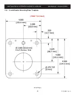
Page 45: ...39 DOC06950 Rev A INSTALLATION OPERATION PARTS CATALOG CleenSweep Manual CSM 11 0 Crank Handle Mounting Plate Template PRINT TO SCALE Final Page Shaft Access Hole ...

Reviews: