background image

Summary of Contents for 179A

Page 1: ...nstruction Manual Model 179A TRMS Multimeter 01982 Keithley Instruments Inc Cleveland Ohio U S A Document Number 32430 Advanced Test Equipment Rentals www atecorp com 800 404 ATEC 2832 Established 198...

Page 2: ...oeak EWI R ONMENT Operating 0 0 55 C 0 to 80 relative humidity up c storage 25T to l35oc POWER 105 125 0 210 250 bvitch selectedl go lO available 50 60 Hz 5 5w Optional B hour batmy pack Model 1788 DI...

Page 3: ...Verification Procedure Initial Conditions DCVoltsVerification AC Volts Verification Resistance Verification DC Current Verification AC Current Verification SECTION 4 THEORY OF OPERATION Introduction O...

Page 4: ...l79A Mother Board PC 492 Parts List 6 2 Model 179A Display Board PC 485 Parts List 6 4 Model 1788 Battery Pack PC 451 Parts List 6 5 Recommended spare parts 6 5 LIST OF FIGURES FIGURE TITLE PAGE 2 1 2...

Page 5: ...ct the Keithley representative in your area to deter mine the proper action lo be taken Keithley maintains come plete repair and calibration facilities in the United States West Germany Great tlritain...

Page 6: ...ith chucks and 4 heavy duty tip plugs 9 Model 1684 Hard Shell Carrying Case Hard vinyl case 1OOmm x 300mm x 350mm 4 x 13 x 14 has a fitted foam insert with room for the Model 179A instruction manual a...

Page 7: ...ed allow it to charge for at least 14 hours NOTE For maximum battery life do not allow the battery pack to remain completely discharg ed Constant charging will not harm either the battery pack or the...

Page 8: ...y are not intended for adjustment during operation Figure 2 l Rear View Showing Line Switch MlNUS SIGN DISPLAYED PLVS SIGN IMPLIED OVERRANGE IS INDICATED BY A FLASHING 0000 EXCEPT ON THE 1000 VOLT RAN...

Page 9: ...ero the instrument as described in paragraph 2 2 2 step 7 Zero the instrument before the first use or whenever the instrument is used outside the temperature range of 18OC to 28OC and weekly during no...

Page 10: ...000mA C Connect the unknown current to the INPUT jacks of 2 Select the HI mode or the LO mode see paragraph 2 2 2 the Model 179A as shown in Figure 2 6 SteD 31 D Note reading on display Figure 2 5 Res...

Page 11: ...must be capable of handling 20A and it is recommended that they be twisted see Figure 2 71 to minimize external fields which could affect the Model 179A or other equipment Also keep the test leads as...

Page 12: ......

Page 13: ...care to prevent con tact with live circuits which could cause electrical shock resulting in injury or death 3 5 INITIAL CONDITIONS Before beginning the verification procedure the instrument must meet...

Page 14: ...t the decade resistor to zero and measure the resistance of the test leads Subtract this reading from the displayed reading in all of the following steps 5 Set the decade resistor to 19 000k12 Verify...

Page 15: ...nput resistance except on the lowest ranges or under overload conditions In the DCA mode the voltage across the shunt resistor is applied to the AID converter with 200mV giving a full scale reading 2...

Page 16: ...ges high frequency compen sation is adjusted with capacitor Cl1 1 as shown in Table 4 3 On the 20V range adjustment is performed with C112 On the 200 and 1000 volt ranges adjustment is performed with...

Page 17: ...rnal integrate period 6 Figure 4 3 is 1OOms In length The A D input is buffered by U104 lsee paragraph 4 6 4 and integrated by U103 Positive signals generate a negative going ramp at the integrator o...

Page 18: ...ance ranges by contacts on the push button switch Proper decimal point position is determined by the combina tion of function and range selected 4 8 CURRENT MEASUREMENTS In the A mode the signal is sw...

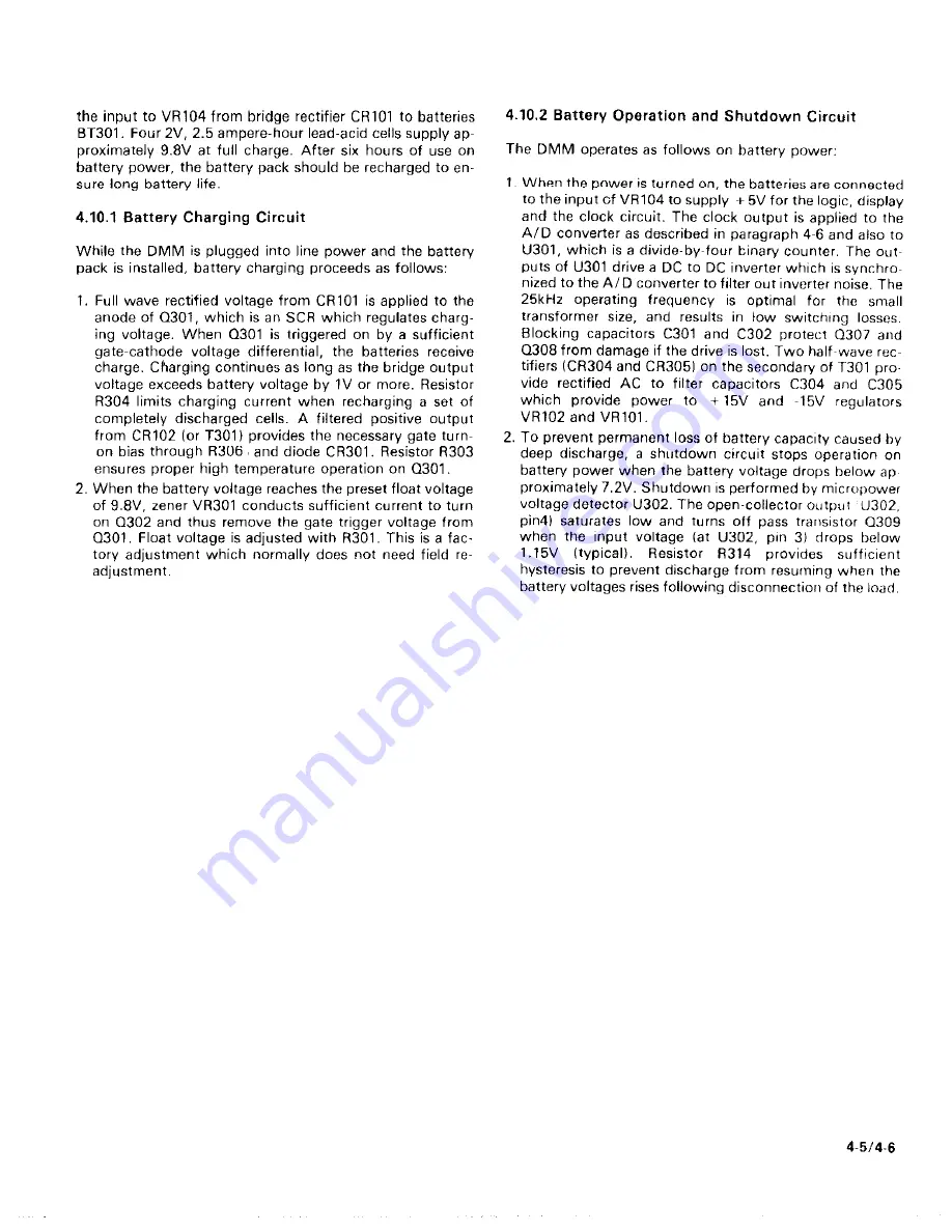
Page 19: ...es not need field re adjustment 4 10 2 Battery Operation and Shutdown Circuit The DMM operates as follows on battery power 1 When the power is turned on the batteries are connected to the input of VR1...

Page 20: ......

Page 21: ...igure 6 1j from the upper side of the battery pack and remove the battery pack from the spacers 3 Calibration may be performed on battery power as long as the battery pack is sufficiently charged Leav...

Page 22: ...n the battery pack plug with connector P1004 on the circuit board Push the plug firmly onto the connector until the lip on the plug engages the lip on the connector to lock the plug in place For instr...

Page 23: ...oard PC 541 Use the schematic diagam and component layout drawing to located these test points 5 5 SPECIAL HANDLING OF STATIC SENSITIVE DEVICES CMOS devices are designed to function at high impedance...

Page 24: ...able 5 6 longer than 30 minutes will reduce bat tery life 4 When cells reach 9 8V turn the Model 179A ON and ad just R301 to maintain 9 8V across BT301 5 Turn the Model 179A OFF disconnect line power...

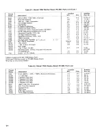
Page 25: ...approximately one year 6 3 ORDERING INFORMATION To place an order or to obtain information concerning replacement parts contact your Keithley representative or the factory See the inside front cover f...

Page 26: ...ray 5V Reed Type Relay 5V Reed Type Relay 5V Reed Type Relay 5V Reed Type Relay 5V Reed Type Relay 8 Pin Male Connector 10 Pin Male Connector 3 Pin Male Connector 8 Pin Male Connector NOT USED NOT USE...

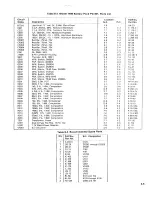
Page 27: ...1 li8W Metal Film Thick Film Network 47kll 10 WW Composition 90 0 5w 0 1 ww SOOR 0 1 112W Metal Film Son 1 2W l Metal Film llkll 1 li8W Metal Film 19 6kII 1 l EW Metal Film 50k12 10 Cermet Trimmer 50...

Page 28: ...E 2 Several G 2 C 8 E 5 C 8 E 5 D 7 D 4 J 2 D 2 F 5 F l J1004 is located on PC 451 1788 Battery Pack1 PlOOl and P1002 are located on PC 485 Display Board R112 may or may not be installed Table 6 2 Mod...

Page 29: ...R 5 114W Composition 1On 5 114W Composition 100kil 5 114W Composition 100kn 5 ll4W Composition 100kR 5 1 4W Composition 6 6MO 10 1 4W Composition 576kI2 1 116W Composition lOOkfl 1 1 6W Composition Tr...

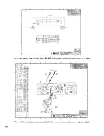
Page 30: ...Y _6 Figure 6 Z Model 179A Display Board PC 485 Component Location Drawing Dwg No 29663 Figure 6 3 Model 1788 Battery Pack PC 451 Component Location Drawing Dwg No 29007 6 6...

Page 31: ...Figure 64 Model 179A Mother Board PC492 Com ponent Location Drawing Dwg No 32045 6 7 6 E...

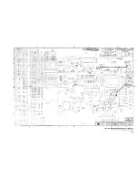
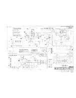
Page 32: ...3 4 i i I DC Figure 6 6 Model 179A and 1788 Schematic Diagram Dwg No 32046 6 916 10...

Page 33: ...SERVICE FORM Model No Serial No Name and Telephone No Company Date List all control settings descrihc problem and check hones lbat apply to problem...

Reviews: