background image


Verifying AC current


Check AC current accuracy by applying accurate AC current at specific frequencies from the 

AC current calibrator to the Model 2010 input and verifying that the displayed readings fall 
within specified limits. Follow these steps to verify AC current:

1.

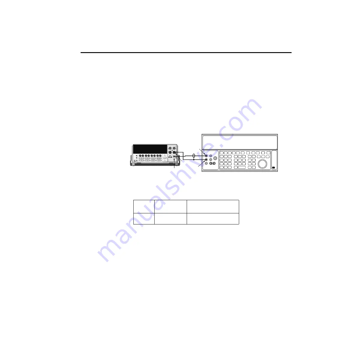
Connect the Model 2010 AMPS and INPUT LO jacks to the calibrator as shown in 

Figure 1-4

2.

Select the AC current function by pressing the ACI key.

3.

Set the Model 2010 for the 1A range.

4.

Source 1A and 2.2A, 1kHz full-scale AC currents as summarized in 

Table 1-5

, and verify 

that the readings are within stated limits.


Table 1-5


ACI limits


ACI 

range

Applied DC 

current

Reading limits

(1 year, 18°C–28°C) 1kHz


1A
3A

1.000000A

2.20000A

0.99860 to 1.00140A

2.1949 to 2.2051A

2000 MULTIMETER

!

R

5700A Calibrator (Output AC Current)

Output HI

Input
LO Output

LO

Model 2010

Amps

Figure 1-4

Connections for AC 
current verification


Performance Verification

1-9

Summary of Contents for 2010

Page 1: ...www keithley com Model 2010 Multimeter Service Manual 2010 902 01 Rev D October 2003 A G R E A T E R M E A S U R E O F C O N F I D E N C E...

Page 2: ...m product modification without Keithley Instruments express written consent or misuse of any product or part This warranty also does not apply to fuses software non rechargeable batteries damage from...

Page 3: ...Model 2010 Multimeter Service Manual 1996 Keithley Instruments Inc All rights reserved Cleveland Ohio U S A Fourth Printing October 2003 Document Number 2010 902 01 Rev D...

Page 4: ...d all Addenda associated with the previous Revision of the manual are incorporated into the new Revision of the manual Each new Revision includes a revised copy of this print history page Revision A D...

Page 5: ...tional Electrotechnical Commission IEC Standard IEC 60664 Most measurement control and data I O signals are Measurement Category I and must not be directly connected to mains voltage or to voltage sou...

Page 6: ...instrument shows that the surface may be hot Avoid personal contact to prevent burns The symbol indicates a connection terminal to the equipment frame If this symbol is on a product it indicates that...

Page 7: ...fying DC voltage 1 6 Verifying AC voltage 1 7 Verifying DC current 1 8 Verifying AC current 1 9 Verifying resistance 1 10 Verifying temperature 1 12 Thermocouple temperature 1 12 RTD temperature 1 13...

Page 8: ...15 Resistance calibration 2 16 DC current calibration 2 17 AC voltage calibration 2 18 AC current calibration 2 18 Programming calibration dates 2 19 Saving calibration constants 2 19 Locking out cali...

Page 9: ...ng states 4 13 No comm link error 4 18 5 Disassembly Introduction 5 2 Handling and cleaning 5 2 Handling PC boards 5 2 Solder repairs 5 2 Static sensitive devices 5 3 Assembly drawings 5 3 Case cover...

Page 10: ...mmands B 12 Manufacturing calibration commands B 14 Remote error reporting B 14 Error summary B 15 Error queue B 17 Status byte EAV Error Available bit B 17 Generating an SRQ on error B 17 Detecting c...

Page 11: ...connections for DC volts and ohms portion of comprehensive calibration 2 8 Figure 2 3 Connections for DC and AC amps comprehensive calibration 2 10 Figure 2 4 Connections for AC volts calibration 2 11...

Page 12: ...mary 2 10 Table 2 6 AC voltage calibration summary 2 11 Table 2 7 AC current calibration summary 2 12 Table 2 8 DC voltage calibration programming steps 2 15 Table 2 9 Resistance calibration programmi...

Page 13: ...and gain 4 17 Table 4 16 4 signal multiplexing and gain 4 17 Table 4 17 Circuit section locations for switching devices 4 17 6 Replaceable Parts Table 6 1 Mother board parts list 6 3 Table 6 2 Display...

Page 14: ...1 Performance Verification 1 Performance Verification...

Page 15: ...the correct course of action Verification test requirements Be sure that you perform the verification tests Under the proper environmental conditions After the specified warm up period Using the corr...

Page 16: ...e 5700A at each source value Table 1 1 Recommended verification equipment Fluke 5700A Calibrator DC voltage AC voltage 1kHz 50kHz DC current AC current 1kHz Resistance 100mV 14ppm 1 0V 7ppm 10V 5ppm 1...

Page 17: ...0V 00024 00004 Reading limits 10V 00028V Reading limits 9 99972V to 10 00028V Calculating resistance reading limits Resistance reading limits must be recalculated based on the actual calibration resis...

Page 18: ...use autoranging for any verification tests because autorange hysteresis may cause the Model 2010 to be on an incorrect range For each test signal you must manually set the correct range for the Model...

Page 19: ...mV range 3 Set the calibrator output to 0 00000mV DC and allow the reading to settle 4 Enable the Model 2010 REL mode Leave REL enabled for the remainder of the DC volts verification tests 5 Source po...

Page 20: ...ed in Table 1 3 and make sure that the respective Model 2010 readings fall within stated limits Table 1 3 ACV reading limits ACV range Applied AC voltage Reading limits 1 year 18 C 28 C 1kHz 50kHz 100...

Page 21: ...ositive and negative full scale currents for each of the ranges listed in Table 1 4 and verify that the readings for each range are within stated limits Table 1 4 DCI limits DCI range Applied DC curre...

Page 22: ...1 4 2 Select the AC current function by pressing the ACI key 3 Set the Model 2010 for the 1A range 4 Source 1A and 2 2A 1kHz full scaleAC currents as summarized in Table 1 5 and verify that the readin...

Page 23: ...5 2 Set the calibrator for 4 wire resistance with external sense on 3 Select the Model 2010 4 wire resistance function by pressing the 4 key 4 Set the Model 2010 for the 10 range and make sure the FIL...

Page 24: ...100M 10 100 1k 10k 100k 1M 10M 100M 9 999310 to 10 000690 99 99390 to 100 00610 0 9999480 to 1 0000520k 9 999480 to 10 000520k 99 99260 to 100 00740k 0 9999260 to 1 0000740M 9 995960 to 10 004040M 99...

Page 25: ...elect a thermocouple type temperature sensor C Press ENTER The unit then displays the thermocouple type TYPE J D Select a type J temperature sensor and then press ENTER The unit displays the reference...

Page 26: ...t the display as follows SENS 4W RTD D Press ENTER and note the unit displays TYPE PT100 E Using the cursor and range keys set the unit for the following display TYPE PT385 F Press ENTER to complete t...

Page 27: ...to 1 000000V DC and turn on its output 5 Press SHIFT then RATIO then select and enable both RATIO ON and SENSEIN ON 6 Verify that the ratio reading is between 0 9999460 and 1 0000540 2000 MULTIMETER...

Page 28: ...2 Calibration 2 Calibration...

Page 29: ...e performed individually if desired NOTE Manufacturing calibration is normally required in the field only if the Model 2010 has been repaired Environmental conditions Conduct the calibration procedure...

Page 30: ...round is 500V peak Exceeding this value may cause a breakdown in insulation creating a shock hazard Some of the procedures in this section may expose you to dangerous voltages Use standard safety prec...

Page 31: ...haracters are anything other than KI you will not be able to unlock cal from the front panel Comprehensive calibration The comprehensive calibration procedure calibrates the DCV DCI ACV ACI and ohms f...

Page 32: ...y other key to return to the calibration process NOTE The Model 2010 will not respond to any remote programming commands while the ABORT CAL message is displayed Table 2 1 Recommended equipment for co...

Page 33: ...ailable calibration menu items until the unit displays RUN and then press ENTER C At the prompt enter the calibration code The default code is 002010 Use the left and right arrow keys to move among th...

Page 34: ...connect the low thermal short properly to the HI LO and SENSE terminals Keep drafts away from low thermal connections to avoid thermal drift which could affect calibration accuracy 2 Press ENTER to st...

Page 35: ...to be turned on Do not exceed 15V peak on sense LO to LO This will cause erroneous readings to be stored during calibration 2 Set the calibrator to output DC volts and turn external sense off 3 Perfo...

Page 36: ...ed in Table 2 4 For each step Set the calibrator to the indicated value and place the unit in operate If the calibrator cannot output the exact resistance value use the Model 2010 left and right arrow...

Page 37: ...Model 2010 display indicates the correct calibration current Press ENTER to complete each step Allow the Model 2010 to finish each step NOTE If you are performing DC only calibration proceed to Settin...

Page 38: ...ating AC volts Even though some calibrators can turn off their external sense the AC voltage can still cause excess voltage to appear between sense LO and LO Table 2 6 AC voltage calibration summary C...

Page 39: ...ft and right arrow keys and the range keys to set the calibration date and then press ENTER 2 The unit will then prompt you to enter the next calibration due date with this prompt CAL NDUE mm dd yy Us...

Page 40: ...ing the completion of each step over the bus The procedures for calibrating the Model 2010 using SCPI commands include Preparing the Model 2010 for calibration Front panel short and open calibration D...

Page 41: ...sending this command CAL PROT CODE KI002010 The above command shows the default code KI002010 Substitute the correct code if changed 6 Send the following command to initiate calibration CAL PROT INIT...

Page 42: ...when calibrating and verifying AC volts NOTE Disconnect sense leads when calibrating and verifying AC volts 2 Perform the calibration steps summarized in Table 2 8 For each step Set the calibrator to...

Page 43: ...resistance or the closest available value Send the indicated programming command Change the command parameter if you are using a different calibration resistance than that shown Wait until the Model 2...

Page 44: ...d the indicated programming command Change the current parameter if you are using a different calibration current Wait until the Model 2010 completes each step before continuing NOTE If you are perfor...

Page 45: ...alibrator to the AMPS and INPUT LO terminals of the Model 2010 as shown in Figure 2 3 2 Perform the calibration steps summarized in Table 2 12 For each step Set the calibrator to the indicated current...

Page 46: ...ration constants After completing the calibration procedure send the following command to save the new calibration constants CAL PROT SAVE NOTE Calibration constants will not be saved unless the SAVE...

Page 47: ...t of the power up cycle Be sure to use the correct procedure as outlined below Recommended test equipment Table 2 13 summarizes the test equipment required for the manufacturing calibration steps Note...

Page 48: ...O EXIT ENTER DIGITS RATE REL FILTER TRIG EX TRIG STORE RECALL OPEN CLOSE DCV DCI MX B dBm ACV ACI 2 4 FREQ TEMP dB CONT PERIOD SENSOR LIMITS ON OFF DELAY HOLD SAVE SETUP CONFIG HALT TYPE RS232 GPIB RA...

Page 49: ...the appropriate calibration code default 002010 4 Select ALL at the CAL RUN prompt 5 Press ENTER 6 Perform the entire front panel comprehensive calibration procedure discussed earlier in this section...

Page 50: ...with the INPUTS switch Allow three minutes for thermal equilibrium 2 Press in and hold the OPEN key while turning on the power 3 Enable calibration by sending the CODE command For example the default...

Page 51: ...to the rear panel input jacks and select the rear inputs with the INPUTS switch Allow three minutes for thermal equilibrium 2 Press in and hold the OPEN key while turning on the power 3 Press SHIFT t...

Page 52: ...libration procedure discussed earlier in this section See Comprehensive calibration earlier in this section 7 Connect the synthesizer to the Model 2010 INPUT jacks as shown in Figure 2 7 Select the fr...

Page 53: ...3 Routine Maintenance 3 Routine Maintenance...

Page 54: ...gure 3 1 Gently push in and turn to the left Release pressure on the assembly and its internal spring will push it out of the power module Model 2010 WARNING NO INTERNAL OPERATOR SERVICABLE PARTS SERV...

Page 55: ...o replace the AMPS fuse WARNING Make sure the instrument is disconnected from the power line and other equipment before replacing the AMPS fuse 1 Turn off the power and disconnect the power line and t...

Page 56: ...4 Troubleshooting 4 Troubleshoot ing...

Page 57: ...unit back to the factory for repairs or limit repairs to the PC board replacement level Without proper equipment and training you could damage a PC board beyond repair Repairs will require various de...

Page 58: ...the second consecutive press of EXIT aborts the test and returns the instrument to normal operation DISP test The display test allows you to verify that each segment and annunciator in the vacuum fluo...

Page 59: ...the line fuse and line voltage selection switch of the power module to the power transformer The power transformer has a total of four secondary windings for the various supplies AC voltage for the di...

Page 60: ...mon CR116 CR117 C108 U101 CR102 C131 C148 U179 U180 CR103 C146 U124 37V D Common 15V A Common 15V 5V 5VRL A Common 18V A Common 18V 25V A Common 25V U187 C279 C281 20V A Common CR102 CR136 CR137 CR138...

Page 61: ...the drivers is serially transmitted from the microcontroller MOSI and PC1 Filament voltage for the display is derived from the power supply transformer F1 and F2 The display drivers require 37VDC and...

Page 62: ...TXDB and RXDB lines of the MPU U159 provides the necessary voltage level conversion for the RS 232 interface port IEEE 488 interface U158 U160 and U161 make up the IEEE 488 interface U158 a 9914A GPIA...

Page 63: ...Q101 and Q102 which disconnects the analog input signal from the rest of the analog circuit Note that for the 100VDC and 1000VDC ranges Q101 and Q102 of the SSP are open The DC voltage signal is route...

Page 64: ...current for OHMS is generated by the Ohms I Source circuit For 4 wire ohms measurements SENSE LO is connected to the circuit by controlling U163 Signal switching and gain for ACV FREQ and ACA is done...

Page 65: ...able 4 2 Display board checks Step Item component Required condition Remarks 1 2 3 4 5 6 7 Front panel DISP test P1005 pin 5 P1005 pin 9 U401 pin 1 U401 pin 43 U401 pin 32 U401 pin 33 Verify that all...

Page 66: ...anode U180 pin 1 U179 pin 2 Q183 emitter Check continuity 120V 240V as required Plugged into live receptacle power on 5V 5 37V 5 15V 5 15 7V 5 5V 5 25V 20 25V 20 18V 20 18V 20 21V 5 Remove to check C...

Page 67: ...91 U135 pin 90 U135 pin 89 RAM OK ROM OK Digital common 5V Low on power up then goes high Check for stuck bits Check for stuck bits 14 7456MHz Pulse train during RS 232 I O Pulse train during RS 232 I...

Page 68: ...53 100mV 1V 10V OFF OFF OFF OFF OFF OFF OFF OFF OFF OFF OFF OFF OFF OFF OFF SET SET SET ON ON ON OFF OFF OFF OFF OFF OFF OFF OFF OFF ON ON ON ON ON ON K101 SET states Pin 8 switched to Pin 7 Pin 3 swi...

Page 69: ...switched to Pin 2 Table 4 8 4 signal switching Range K104 Q101 Q102 Q114 Q136 Q109 K101 K102 Q113 Q105 Q104 Q108 Q153 Q167 10 100 1k 10k 100k 1M 10M 100M RESET RESET RESET RESET RESET RESET RESET RES...

Page 70: ...OFF OFF OFF OFF ON ON ON ON ON OFF OFF OFF ON ON ON ON ON Dry circuit 10 100 ON OFF OFF ON ON OFF ON OFF OFF ON OFF ON Table 4 10 DCA signal switching Range K103 Q165 Q164 10mA 100mA 1A 3A ON ON OFF...

Page 71: ...plexing and gain Range Signal U163 U176 pin 1 U176 pin 8 U176 pin 9 Gain U177 U129 pin 16 100mV 1V 10V 100V 1000V S4 S4 S4 S4 S4 OFF OFF OFF OFF OFF OFF OFF ON OFF ON OFF ON OFF ON OFF X100 X10 X1 X10...

Page 72: ...ignal U163 U176 pin 1 U176 pin 8 U176 pin 9 Gain U177 U176 pin 16 10 100 1k 10k 100k 1M 10M 100M S4 then S7 S4 then S7 S4 then S7 S4 then S7 S4 then S7 S4 then S7 S4 then S7 S4 then S7 OFF OFF OFF OFF...

Page 73: ...Turn off the power and disconnect the line cord and all other test leads and cables from the instrument 2 Remove the case cover as outlined in Section 5 3 Find the two firmware ROMs U156 and U157 loc...

Page 74: ...5 Disassembly 5 Disassembly...

Page 75: ...nly handle PC boards by the edges and shields Do not touch any board traces or components not associated with repair Do not touch areas adjacent to electrical contacts Use dry nitrogen gas to clean du...

Page 76: ...at a properly grounded work station Also ground yourself with a suitable wrist strap Handle the devices only by the body do not touch the pins Ground any printed circuit board into which a semiconduc...

Page 77: ...the two captive screws that secure the rear bezel to the chassis Pull the bezel away from the case 4 Removing Grounding Screws Remove the two grounding screws that secure the case to the chassis They...

Page 78: ...d This procedure assumes that the case cover is already removed 1 Remove the IEEE 488 and RS 232 fasteners The IEEE 488 and the RS 232 connectors each have two nuts that secure the connectors to the r...

Page 79: ...d the mounting screw Tighten all the fasteners once they are all in place and the board is correctly aligned 6 Remove the motherboard which is held in place by edge guides on each side by sliding it f...

Page 80: ...following WARNING Disconnect the instrument from the power lines and remove the test leads before changing the firmware 1 Remove the case cover as described earlier in this section 2 Locate U156 EVEN...

Page 81: ...ransformer to the bottom of the chassis 4 Pull the black ground wire off the threaded stud and remove the power transformer from the chassis WARNING To avoid electrical shock which could result in inj...

Page 82: ...er module be sure to re connect the green and yellow ground wire to the threaded stud on the chassis Instrument re assembly Re assemble the instrument by reversing the previous disassembly procedures...

Page 83: ...CONFIDENTIAL PROPRIETARY...

Page 84: ......

Page 85: ......

Page 86: ......

Page 87: ...6 Replaceable Parts 6 Replaceable Parts...

Page 88: ...include the following information Instrument model number Model 2010 Instrument serial number Part description Component designation if applicable Keithley part number Factory service If the instrume...

Page 89: ...P 100UF 20 63V ALUM ELEC CAP 22UF 20 400V FILM CAP 15P 1 100V CERAMIC CAP 1UF 20 50V CERAMIC CAP 2 2UF 20 63V POLYCARB CAP 47P 5 100V CERAMIC CAP 01 5 50V NPO CAP 1000P 10 100V CERAMIC CAP 33UF 20 63V...

Page 90: ...IODE SWITCHING MMSD914T19 SURGE ARRESTOR CG3 1 5L CONN MICRODIN W GND FINGERS CONN RT ANGLE MALE 9 PIN CONN RIGHT ANGLE 24 PIN CONN HEADER STRAIGHT SOLDER PIN CONNECTOR HEADER CONN MALE 5 PIN MOLEX 42...

Page 91: ...TRANS DUAL PNP LS352 TRANS PNP BC860C TRANS N CHAN MOSFET IRF7101 TRANS N CHANNEL FET 2N4392 TRANS P CHAN MMBFJ175 RES 1M 5 125MW METAL FILM RES 549K 1 1 4W METAL FILM RES 11K 1 1 10W METAL FILM RES...

Page 92: ...FILM RES 475 1 100MW THICK FILM RES 5 11K 1 100MW THICK FILM RES 34K 1 100MW THICK FILM RES 10 10 100MW THICK FILM RES 82 5 1 100MW THICK FILM RES 4 02K 1 100MW THICK FILM RES 200 1 100MW THICK FILM...

Page 93: ...M 10 1 2W 1 5KV METAL OXIDE RES 137 1 125MW METAL FILM RES 4 02K 1 100MW THICK FILM RES 49 9K 1 100MW THICK FILM RES 1 87K 1 1 8W METAL FILM RES 200 1 1 10W METAL FILM RES 100K 1 100MW THICK FILM RES...

Page 94: ...QUAD 2 IN NOR 74HCT02 IC NCHAN LAT DMOS QUADFET SD5400CY IC OPTOCOUPLER 2601 IC 32KX8 STAT CMOS RAM D43256C IC QUAD D FLIP FLOP W CLK RESET 74HC175 PROGRAMMED ROM PROGRAMMED ROM IC GPIB ADAPTER 9914A...

Page 95: ...ODE ZENER 3 3V MMBZ5226BL DIODE ZENER 6 2V BZX84B6V2 DIODE ZENER 6 4V IN4579 DIODE ZENER 12V MMSZ11T1 DIODE ZENER 7 5V BZX84C7V5 CRYSTAL 14 7456MHZ OSCILLATOR HIGH SPEED CMOS 12MHZ DZ 100 DZ 103 DZ 97...

Page 96: ...10K 1 100MW THICK FILM RES 13K 1 100MW THICK FILM RES 15K 1 100MW THICK FILM PROGRAMMED ROM IC LATCHED DRIVERS UCN 5812EPF 1 IC 8 BIT MICROCON MC68HC705C8P PLCC CRYSTAL 4MHZ C 417 22 C 418 1 C 451 33P...

Page 97: ...EAR SWITCH ROD FUSE HOLDER FUSE 0 25A FUSE 3A 250 JACK CURRENT INPUT JACK CURRENT INPUT LINE MODULE MOTHERBOARD SHIELD MOUNTING EAR LEFT MOUNTING EAR RIGHT POWER ROD REAR PANEL SWITCHPAD TRANSFORMER W...

Page 98: ...CONFIDENTIAL PROPRIETARY...

Page 99: ...CONFIDENTIAL PROPRIETARY...

Page 100: ......

Page 101: ...A Specifications A Specifications...

Page 102: ...ERISTICS 3 FUNCTION DIGITS READINGS s PLCs 7 DCV all ranges 71 2 2 4 3 5 DCI all ranges and 61 2 2 6 30 27 1 Ohms 10M range 61 2 2 4 50 44 1 51 2 2 4 260 220 0 1 51 2 4 490 440 0 1 51 2 4 1000 1000 0...

Page 103: ...and sinewave inputs 5 of range 2 Speeds are for 60Hz 50Hz operation using factory default operating conditions RST Auto zero off Auto range off Display off includes measurement and binary data transfe...

Page 104: ...uto Range off Display off sample count 1024 2 NPLC 0 01 3 DETector BANDwidth 300 Triggering and Memory READING HOLD SENSITIVITY 0 01 0 1 1 or 10 of reading TRIGGER DELAY 0 to 99 hrs 1ms step size EXTE...

Page 105: ...84V to 5 00016V DC current and resistance calculations are performed in exactly the same manner using the pertinent specifications ranges and input signal values Calculating AC characteristics accurac...

Page 106: ...rs must be applied to calculate certain accuracy values For example an additional derating factor of 0 02ppm V must be added to DCV specifications for voltages over 500V Before calculating accuracy st...

Page 107: ...B Calibration CommandReference B Calibration CommandRef erence...

Page 108: ...ed CODE up to 8 char string COUNt INITiate LOCK LOCK SAVE DATE year month day DATE NDUE year month day NDUE Calibration root command All commands in this subsystem are protected by the calibration loc...

Page 109: ...teps 10mV AC at 1kHz step 100mV AC at 1kHZ step 100mV AC at 50kHz step 1V AC at 1 kHz step 1V AC at 50kHz step 10V AC at 1kHz step 10V AC at 50kHz step 100V AC at 1kHz step 100V AC at 50kHz step 700V...

Page 110: ...ufacturing calibration command The default calibration code is KI002010 Note The CODE command should be sent only once before performing either the comprehensive or factory calibration Do not send COD...

Page 111: ...cal prot lock Description The LOCK command lets you lock out both comprehensive and manufacturing calibration after completing those procedures Thus LOCK performs the opposite of enabling calibration...

Page 112: ...alibration constants Example CAL PROT SAVE Save calibration constants DATE CALibration PROTected DATE Purpose To send the calibration date to the instrument Format cal prot date year month day Paramet...

Page 113: ...ar month day Description The NDUE command allows you to store the date when calibration is next due in instrument memory You can read back the next due date from the instrument over the bus by using t...

Page 114: ...t circuit calibration Table B 2 DC calibration commands Command Description Parameter limits CALibration PROTected DC STEP1 STEP2 STEP3 NRf STEP4 NRf STEP5 NRf STEP6 NRf STEP7 NRf STEP8 NRf STEP9 NRf...

Page 115: ...d for best results Example CAL PROT DC STEP3 10 Program 10V step STEP4 CALibration PROTected DC STEP4 Purpose To program the 10V DC comprehensive calibration step Format cal prot dc step4 Cal_voltage...

Page 116: ...mended for best results Example CAL PROT DC STEP7 1E3 Program 1k step STEP8 CALibration PROTected DC STEP8 Purpose To program the 10k 4 wire comprehensive calibration step Format cal prot dc step8 Cal...

Page 117: ...10E 3 value whenever possible for best results Example CAL PROT DC STEP11 10E 3 Program 10mA step STEP12 CALibration PROTected DC STEP12 Purpose To program the 100mA comprehensive calibration step Fo...

Page 118: ...13 10mV AC at 1kHz calibration step 100mV AC at 1kHZ calibration step 100mV AC at 50kHz calibration step 1V AC at 1 kHz calibration step 1V AC at 50kHz calibration step 10V AC at 1kHz calibration step...

Page 119: ...alibration step 8 100V AC at 1kHz calibration step 9 100V AC at 50kHz calibration step 10 700V AC at 1kHz calibration step 11 100mA AC at 1kHz calibration step 12 1A AC at 1kHz calibration step 13 2A...

Page 120: ...calibration steps The appropriate signal must be connected to the instrument when programming each step as summarized by the parameters listed above Examples CAL PROT AC STEP14 1 Program AC step 14 CA...

Page 121: ...error 10M 2 w zero error 10M 2 w full scale error 10M 2 w open error 1k 4 w zero error 10k 4 w zero error 100k 4 w zero error 10M 4 w sense lo zero error 1k 4 w full scale error 10k 4 w full scale err...

Page 122: ...or Frequency gain error 10 vdc sense zero error 10 2 w zero error 10 4 w zero error 10 4 w full scale error 1 adc zero error 10 Ohm DryCkt Zero error 10 Ohm DryCkt FS error 100 Ohm DryCkt Zero error 1...

Page 123: ...en read the status byte and error queue as outlined above to check for errors and to determine the exact nature of the error Detecting calibration step completion When sending remote calibration comma...

Page 124: ...d 3 After sending a calibration command repeatedly test the ESB Event Summary bit bit 5 in the status byte until it is set Use either the STB query or serial polling to request the status byte 4 Once...

Page 125: ...C Calibration Program C Calibration Program...

Page 126: ...C PC 488 IEEE 488 interface for the computer Two shielded IEEE 488 connecting cables Keithley Model 7007 Software requirements In order to use the calibration program you will need the following softw...

Page 127: ...Use the front panel GPIB key to check or change the address 4 Make sure the calibrator primary address is at its factory default setting of 4 5 Make sure that the computer bus driver software CECHP EX...

Page 128: ...rtial command header CLS Clear CRT PRINT Model 2010 Multimeter Comprehensive Calibration Program PRINT 1 OUTPUT 16 CAL PROT CODE KI002010 Send KI002010 cal code PRINT 1 OUTPUT 16 CAL PROT INIT Initiat...

Page 129: ...ErrCheck PRINT 1 OUTPUT 16 CAL PROT SAVE Save calibration constants GOSUB ErrCheck PRINT 1 OUTPUT 16 CAL PROT LOCK Lock out calibration PRINT Calibration completed PRINT 1 OUTPUT 16 SYST PRES END KeyC...

Page 130: ...from inputs DC STEP2 DATA OUT 10 V 0 HZ DC STEP3 10 DATA OUT 10 V DC STEP4 10 DATA OUT 100 V DC STEP5 100 DATA OUT 10 OHM DC STEP6 DATA OUT 1 KOHM DC STEP7 DATA OUT 10 KOHM DC STEP8 DATA OUT 100 KOHM...

Page 131: ...ctions for firmware revision A14 and higher 2 21 D DC calibration commands B 8 DC current calibration 2 10 2 17 DC volts calibration 2 8 2 15 Detecting calibration step completion B 17 Digital circuit...

Page 132: ...bration firmware A14 and higher 2 23 Removing power components 5 8 Repair considerations 4 2 Replaceable Parts 6 1 Replacing the AMPS fuse 3 3 Resistance calibration 2 9 2 16 Restoring factory default...

Page 133: ...ble Will not read applied input Overload Calibration only Certificate of calibration required Data required attach any additional sheets as necessary Show a block diagram of your measurement system in...

Page 134: ...ll other trademarks and trade names are the property of their respective companies A G R E A T E R M E A S U R E O F C O N F I D E N C E Keithley Instruments Inc Corporate Headquarters 28775 Aurora Ro...

Reviews: