Model 2701 Service Manual
Calibration
2-7
Front panel short and open calibration
At the Model 2701 prompt for a front panel short, perform the following:
1.
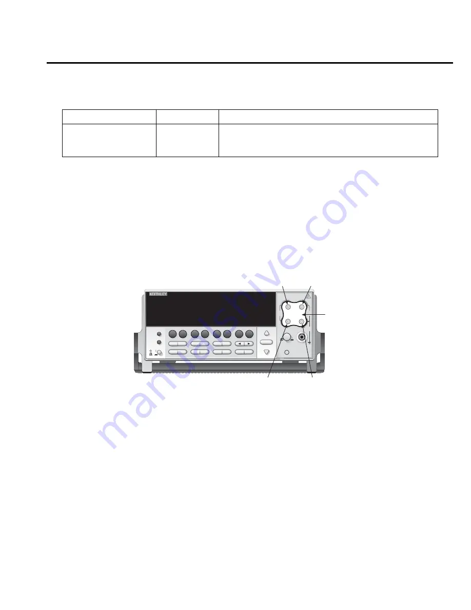
Connect the Model 8610 low-thermal short to the instrument front panel INPUT and
SENSE terminals as shown in
Figure 2-1
. Make sure the INPUTS button is not pressed
in so that the front inputs are selected. Wait at least three minutes before proceeding to
allow for thermal equilibrium.
Figure 2-1
Low thermal short connections
NOTE
Be sure to connect the low-thermal short properly to the HI, LO, and SENSE termi-
nals. Keep drafts away from low-thermal connections to avoid thermal drift, which
could affect calibration accuracy.
2.
Press ENTER to start short-circuit calibration. While the unit is calibrating, it will
display:
CALIBRATING
3.
When the unit is finished with short-circuit calibration, it will display the following
prompt:
OPEN CIRCUIT
4.
Remove the calibration short and press ENTER. During this phase, the
CALIBRATING message will be displayed.
NOTE
Be sure to minimize movement near front Input terminals. Excessive movements can
cause capacitive coupling errors, which could affect calibration accuracy.
Table 2-2
Comprehensive calibration procedures
Procedure
Menu choice
Procedures
Full calibration
DCV, DCI, and ohms
ACV and ACI
ALL
DC
AC
All comprehensive calibration steps (DC and AC)
DC voltage, DC current, and resistance calibration
AC voltage and AC current calibration
!
Model 2701 Ethernet Multimeter / Data Acquisition System
RANGE
F
500V
PEAK
FRONT/REAR
3A 250V
AMPS
HI
INPUT
LO
SENSE
Ω
4 WIRE
INPUTS
350V
PEAK
1000V
PEAK
AUTO
SHIFT
LOCAL
POWER
RANGE
R
EXIT
ENTER
DIGITS RATE
REL
FILTER
TRIG
EX TRIG
STORE RECALL
OPEN
DCV
DCI
MATH
O U T P U T
RATIO
ACV
ACI
Ω
2
Ω
4
FREQ
TEMP
CH AVG
CONT
PERIOD SENSOR
LIMITS
ON/OFF
DELAY
HOLD
SAVE
SETUP
CONFIG
HALT
TYPE
LSYNC
TEST
MONITOR
STEP
SCAN
OCOMP
CH-OFF
CARD
CLOSE
Integra Series
RS-232
ETHERNET
Model 8610
Low-thermal
short
HI
S-
Model 2701
LO
S+
CAT I
Summary of Contents for 2701
Page 15: ...1 PerformanceVerification...
Page 47: ...2 Calibration...
Page 70: ...3 RoutineMaintenance...
Page 78: ...4 Troubleshooting...
Page 97: ...5 Disassembly...
Page 104: ......
Page 105: ......
Page 106: ......
Page 107: ......
Page 108: ......
Page 109: ......
Page 110: ......
Page 111: ...6 ReplaceableParts...
Page 125: ......
Page 126: ......
Page 127: ......
Page 128: ......
Page 129: ......
Page 130: ......
Page 131: ...A Specifications...
Page 140: ...B CalibrationReference...


