Model 2701 User’s Manual
Limits and Digital I/O
9-15
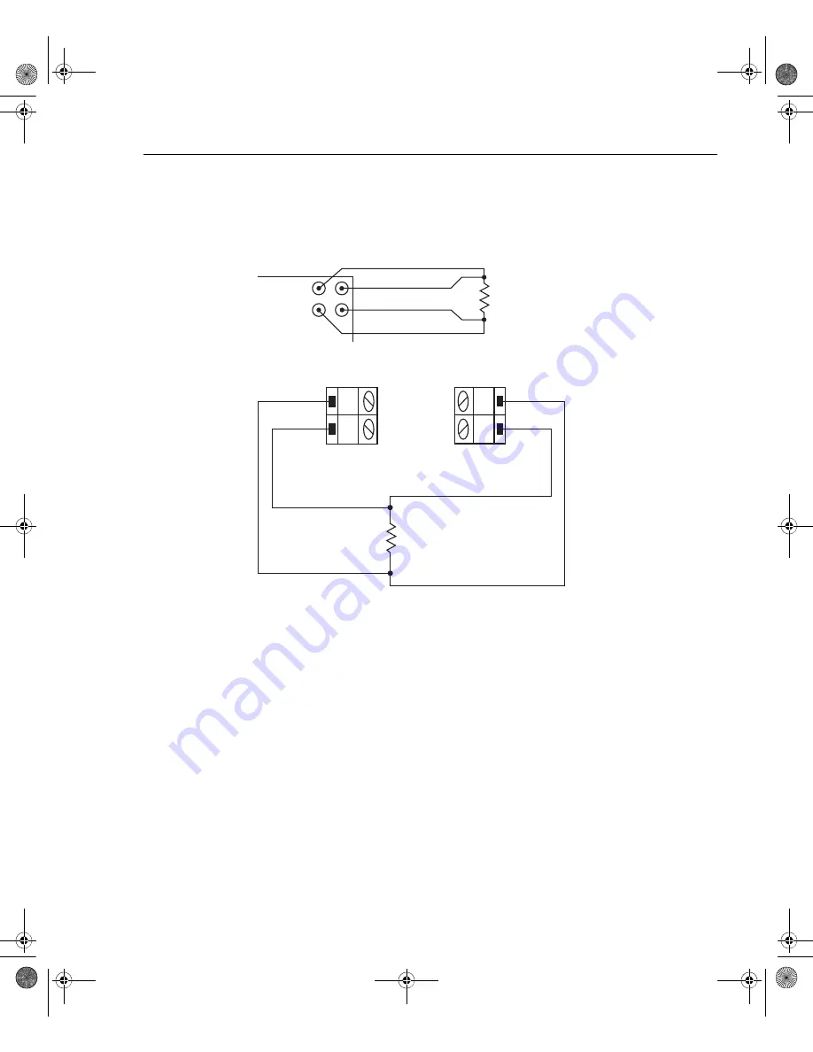
Figure 9-6
Setup to test 100
Ω
resistors
Limit 1 will be used to test for the 1% tolerance and Limit 2 will be used to test for the 5%
tolerance.
The resistance values for the 1% and 5% tolerances are calculated as follows:
R
1%
= 100
Ω
×
1%
R
5%
= 100
Ω
×
5%
= 100
Ω
×
0.01
= 100
Ω
×
0.05
= 1
Ω
= 5
Ω
The high and low limits are then calculated as follows:
HI Limit 1 = 100
Ω
+ R
1%
HI Limit 2 = 100
Ω
+ R
5%
= 100
Ω
+ 1
Ω
= 100
Ω
+ 5
Ω
= 101
Ω
=
105
Ω
LO Limit 1 = 100
Ω
– R
1%
LO Limit 2 = 100
Ω
– R
5%
= 100
Ω
– 1
Ω
=
100
Ω
– 5
Ω
= 99
Ω
= 95
Ω
H
L
CH 1-10
Model 7700
Switching
Module
H
L
CH 11-20
B) Model 7700
INPUT
SENSE
Model 2701
Input HI
Input LO
Sense HI
Sense LO
A) Front panel inputs
100
Ω
100
Ω
2701-900-01.book Page 15 Wednesday, August 3, 2011 9:43 AM
Summary of Contents for 2701
Page 344: ...12 CommonCommands 2701 900 01 book Page 1 Wednesday August 3 2011 9 43 AM...
Page 366: ...15 SCPIReferenceTables 2701 900 01 book Page 1 Wednesday August 3 2011 9 43 AM...
Page 393: ...A Specifications 2701 900 01 book Page 1 Wednesday August 3 2011 9 43 AM...
Page 399: ...B Model7700ConnectionGuide 2701 900 01 book Page 1 Wednesday August 3 2011 9 43 AM...
Page 410: ...C StatusandErrorMessages 2701 900 01 book Page 1 Wednesday August 3 2011 9 43 AM...
Page 417: ...D SignalProcessing SequenceandDataFlow 2701 900 01 book Page 1 Wednesday August 3 2011 9 43 AM...
Page 430: ...E MeasurementConsiderations 2701 900 01 book Page 1 Wednesday August 3 2011 9 43 AM...
Page 450: ...G KE2700InstrumentDriver Examples 2701 900 01 book Page 1 Wednesday August 3 2011 9 43 AM...


