Section 4: Pulse card concepts
Model 4200A-SCS Pulse Card (PGU and PMU) User's Manual
4-16
4200A-PMU-900-01 Rev. A December 2020
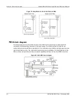
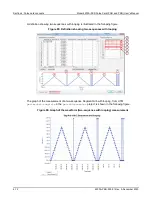
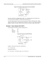
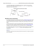
Figure 88: Schematic of pulse channel and connected DUT
As shown in the figure, the voltage across the DUT, V
DUT
, is directly related to the resistance R
DUT
.
The discussion here is simplified, including resistive impedances only.
The 50 Ω output resistance of the pulse channel and the DUT resistance effectively make a voltage
divider. Ohm’s law is the only concept required to determine I
DUT
and V
DUT
in this simple non-dynamic
approach. Calculate the current, and then use the current to calculate the voltage across the DUT.
Example 1: Ideal situation (50 Ω DUT)
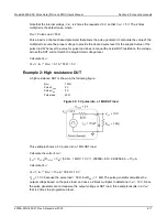
The ideal situation (50 Ω DUT) is shown in the figure below.
R
DUT
50 Ω
Pulse V
HIGH
5 V
Pulse V
LOW
0 V
Pulse load
50 Ω
Figure 89: 5 V pulse into a
50 Ω DUT load
Example 1, showing a 5 V pulse into a 50 Ω DUT load.
V = I * R (Ohm’s Law)
Calculate the current, I
DUT
:
I
DUT
= V
TOTAL
/R
TOTAL
= V
INT
/ (50 Ω + 50 Ω) = 10 V / 100 Ω = 0.1 A

