Section 4: Pulse card concepts
Model 4200A-SCS Pulse Card (PGU and PMU) User's Manual
4-18
4200A-PMU-900-01 Rev. A December 2020
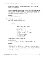
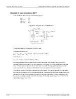
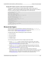
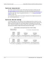
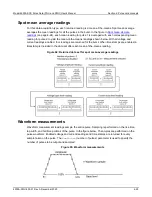
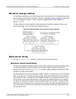
Example 3: Low resistance DUT
A low resistance DUT is shown in the following figure.
R
DUT
5 Ω
Pulse V
HIGH
5 V
Pulse V
LOW
0 V
Pulse load
50 Ω
Figure 91
: 5 V pulse into a 5 Ω DUT load
This figure shows a 5 V pulse into a 5 Ω DUT load.
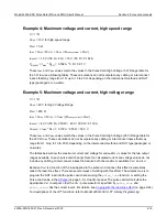
Calculate the current, I
DUT
:
I
DUT
= V
TOTAL
/R
TOTAL
= V
INT
/ (50 Ω + 5 Ω) = 10 V / 55 Ω = 0.182 A
Calculate V
DUT
:
V
DUT
= I
DUT
* R
DUT
= 0.182 A * 1E6 Ω = 0.91 V
All pulse parameters were constant across all three examples. Only the DUT load (R
DUT
) was
changed, resulting in a range of V
DUT
from less than 1 V to nearly 10 V, with corresponding changes
in I
DUT
. This variation is related to the constant pulse load = 50 Ω. Reprogramming the pulse load
value to match R
DUT
would prevent this behavior, but is not practical in many situations.
This effect is inherent to the pulse generator and DUT system. The general approach for calculating
the current and voltage is given in the examples above. Calculating the maximum voltage and current
available for any given DUT resistance is similar to the above examples. The only difference is that
the maximum voltage available is used for the range. For the high-speed range, V
MAX
= 10 V, for the
high voltage range, V
MAX
= 40 V.


