Section 8: Testing flash memory
Model 4200A-SCS Pulse Card (PGU and PMU) User's Manual
8-4
4200A-PMU-900-01 Rev. A December 2020
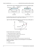
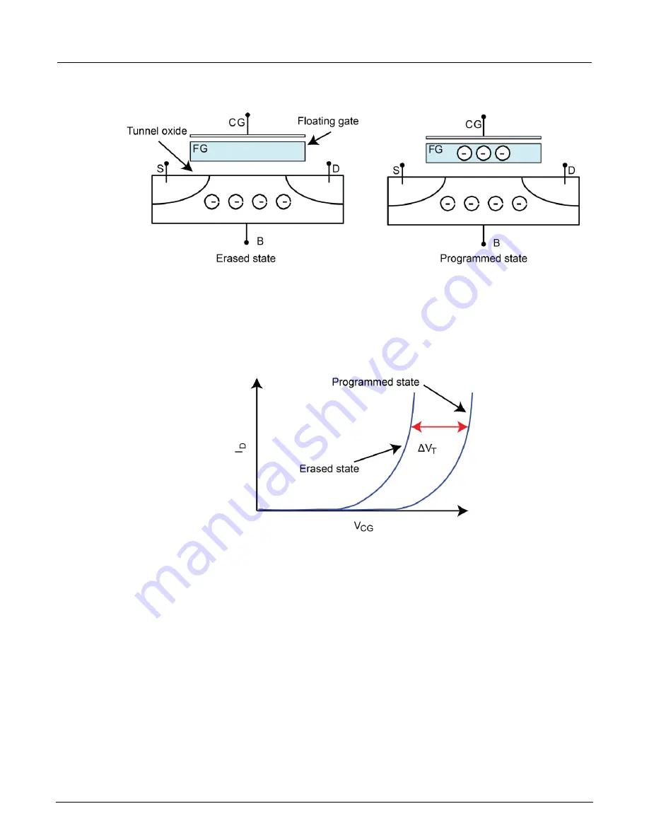
Figure 155: Cross section of a floating gate transistor in the erased and programmed states
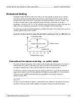
The control gate (CG) reads, programs, and erases the FG transistor. The presence of charge on the
gate shifts the voltage threshold (V
T
) to a higher voltage, as shown below.
Figure 156: Graph of shifted voltage threshold, VT, due to stored charge on floating gate on a
1 bit (2 level) cell
The Flash transistors tests consist of two parts:
1. Pulse waveforms that program or erase the DUT
2. DC measurements are made to determine the state of the device
This implies switching between two conditions:
1. Pulse resources are connected to the DUT
2. Pulse resources are disconnected and the DC resources are connected to the DUT
The pulses are used to move charge to or from the floating gate. There are two different
methods to move charge:
1. Tunneling
2. Hot charge injection (HCI)

