In this section:
Introduction .............................................................................. 3-1
Configure the PGU, PMU, and RPM using tests ...................... 3-1
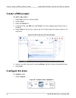
Create a PMU project ............................................................... 3-2
Configure the tests ................................................................... 3-2
PMU operation modes ............................................................. 3-4
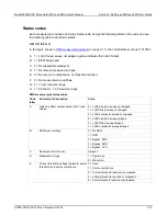
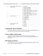
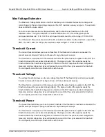
PMU - all terminal parameters .................................................. 3-6
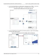
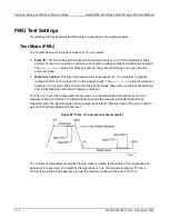
PMU Test Settings ................................................................. 3-16
PMU pulse timing preview ...................................................... 3-24
Pulse parameter definitions .................................................... 3-34
PMU minimum settling times versus current measure range . 3-34
PMU capacitive charging/discharging effects ......................... 3-35
PMU and RPM measure ranges are not source ranges ......... 3-38
4220-PGU and 4225-PMU output limitations ......................... 3-39
Configure the PGU, PMU, and RPM using tests .................... 3-39
Step or sweep multiple device terminals in the same test ...... 3-40
Basic troubleshooting procedure ............................................ 3-43
Introduction
This section provides basic information on creating a PMU project in Clarius and specific information
on the options available for PMUs and PGUs.
For additional detail on working with Clarius, refer to the M
odel 4200A-SCS Clarius User's Manual
.
Configure the PGU, PMU, and RPM using tests
To configure and control the PGU, a user test module (UTM) is needed. You can also use UTMs to
configure and control the PMU and RPM preamplifier. For UTM programming, see “LPT commands
for PGUs and PMUs” in
Model 4200A-SCS LPT Library Programming
.
You can use interactive test modules (ITMs) to configure and control a PMU and RPM preamplifier.
Refer to “Configure a simple test” in
Model 4200A-SCS Clarius User's Manual
for information on
configuring an ITM for the PMU.
An ITM automatically controls the RPM based on the type of test (pulse, CV, SMU). RPM switching
can only be controlled using the
rpm_config
LPT function in a UTM. Refer to
(on page 2-8) for details.
For automatic switching of the RPM in ITMs, the RPM must already have all instrument cabling
connected and recognized by the system. Information on performing this update is in “Update the
RPM configuration” in
Model 4200A-SCS Setup and Maintenance
.
Section 3
Setting up PMUs and PGUs in Clarius

