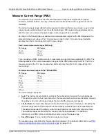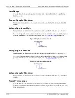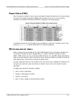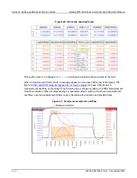
Section 3: Setting up PMUs and PGUs in Clarius
Model 4200A-SCS Pulse Card (PGU and PMU) User's Manual
3-14
4200A-PMU-900-01 Rev. A December 2020
F
Voltage measure overflow and current
measure overflow
0 = No overflow
1 = Negative voltage overflow
2 = Positive voltage overflow
4 = Negative current overflow
5 = Negative voltage and negative current overflow
6 = Positive voltage and negative current overflow
8 = Positive current overflow
9 = Negative voltage and positive current overflow
A = Positive voltage and positive current overflow
G
Current measure range
0 = 100 nA (RPM only)
1 = 1 µA (RPM only)
2 = 10 µA (RPM only)
3 = 100 µA
4 = 1 mA (RPM only)
5 = 10 mA
6 = 200 mA
7 = 800 mA
H
Channel number and voltage
measure range
1 = Ch1, 10 V
2 = Ch2, 10 V
5 = Ch1, 40 V
6 = Ch2, 40 V
Compensation Short Connection
Use to enable or disable short connection compensation. Refer to
page 2-18) for detail on setting up and using connection compensation.
Load Line Effect Compensation
Use to enable or disable load-line effect compensation (LLEC). Refer to
compensation (LLEC) for the PMU
(on page 2-21) for detail on setting up and using load-line effect
compensation.
DUT Resistance (R DUT)
The DUT resistance value. Refer to
DUT resistance determines pulse voltage across DUT
4-15) for detail on calculating DUT resistance.

