Section 3: Setting up PMUs and PGUs in Clarius
Model 4200A-SCS Pulse Card (PGU and PMU) User's Manual
3-26
4200A-PMU-900-01 Rev. A December 2020
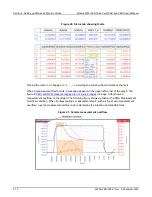
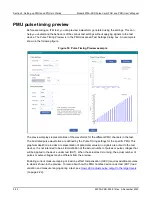
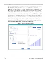
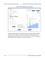
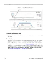
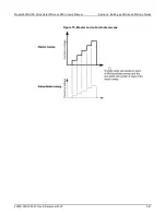
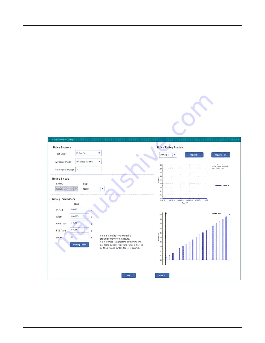
The following figure illustrates the configuration of a six-step pulse amplitude sweep. In this sweep,
the PMU Advanced Settings dialog box (see previous figure) defines the test parameters.
In the Pulse Timing Preview, there are two graphs. The bottom graph, labeled “Entire Test,” shows
the complete test. This graph shows each sweep and step point for the entire test. The graphed
points reflect the PMU Advanced Settings for the PMU channel in the test. The cursor (the pair of
vertical black lines on the Entire Test graph) defines the content of the upper graph (the upper graph
is labeled “Expanded View”). Note that the test from the previous figure defines the six sweep points
that are shown in the bottom graph of the following figure as six pulse periods. In this example, the
pulse periods have voltage amplitude increasing from 0 V to 5 V (this is defined in previous figure).
The other graph, labeled “Expanded View,” provides in-depth information on the section designated
by the cursor lines (on the graph labeled “Entire Test”). The graphed points reflect the timing
parameters (Pulse Timing Preview) and settings from the PMU Advanced Settings dialog box for
each PMU channel in the test, but only for the area specified by the cursor.
Figure 56: Six-point pulse amplitude sweep

