Section 4: Pulse card concepts
Model 4200A-SCS Pulse Card (PGU and PMU) User's Manual
4-20
4200A-PMU-900-01 Rev. A December 2020
Test device resistanc
e (Ω)
Voltage (V)*
Current (A)*
1
0.196
0.196
5
0.909
0.182
10
1.667
0.167
25
3.333
0.133
50
5
0.100
100
6.667
0.067
250
8.333
0.033
1 k
9.524
0.0095
10 k
9.950
0.000995
* Approximate value; does not account for interconnect losses.
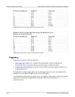
Available I and V for the high voltage (20 V) range of the Keithley pulse card
Maximum I and V versus resistance
Test device resistance (Ω)
Voltage (V)*
Current (A)*
1
0.784
0.784
5
3.636
0.727
10
6.667
0.667
25
13.333
0.533
50
20
0.400
100
26.667
0.267
250
33.333
0.133
1 k
38.095
0.038
10 k
39.801
0.00398
*Approximate value; does not account for interconnect losses.
Triggering
Triggering is used for the following operations:
•
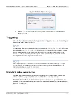
(on page 4-21): Configure the Keithley pulse card for the trigger mode
(Continuous, Burst or Trig Burst) and use a software trigger to start pulse output.
•
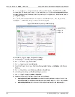
(on page 4-22): Synchronize the pulse-measure operation of a
pulse generator card.
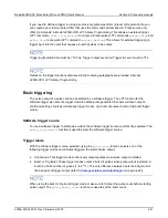
For each pulse in a test, a trigger pulse is sent to the trigger output. If you are using Segment Arb
waveforms, you can define if a trigger out is sent for each segment.
The 4220-PMU and 4225-PGU are trigger out only (no trigger in). These pulse cards use the internal
trigger bus for output synchronization when using any commands that require the
pulse_exec()
function to execute.

