Model 4200A-SCS Pulse Card (PGU and PMU) User's Manual
Section 2: Connections
4200A-PMU-900-01 Rev. A December 2020
2-3
Cable length
Use the shortest possible cable length to achieve the highest frequency output, the best pulse shape,
and the best results. Here are reasons to avoid using longer cable lengths:
•
Longer cable lengths have longer reflection times, which can slow down transmission times.
•
Longer cables may have impedance mismatches, which can cause distortions.
•
Higher capacitance in longer cables causes higher capacitive charging effects during the pulse
PMU capacitive charging/discharging effects
(on page 3-35)).
Only use the white SMA coaxial cables that are supplied with the PMU and RPM. These are 50 Ω
cables that match the internal 50 Ω resistance of the PMU. The PMU is supplied with 6.5 ft (2 m) SMA
cables and the RPM is supplied with 8 in. (20 cm) SMA cables. Always use the 8 in. (20 cm) SMA
cables with the RPM.
High frequency connections
Use these connection guidelines for high-speed testing (pulse width <1 µs).
•
Use cables and connectors optimized for high frequency (at least 150 MHz). The SMA coaxial
cables supplied with the PMU and RPM are rated for high frequency.
•
Probe manipulators must be rated at least 150 MHz.
•
Properly connect the shields of the coaxial cables and minimize the loop area of the shield
(on page 2-2)).
•
(on page 2-3)).
•
Use a signal path that matches the impedance of the instrument (50
Ω). The SMA cables
supplied with the PMU and RPM are 50
Ω.
Prober chuck connections
When possible, avoid pulse connections to the prober chuck. If unavoidable, use these guidelines
when connecting to the prober chuck:
•
When making connections to the back side of the wafer, PMU functionality will be diminished.
Use caution and verify waveforms.
•
Generally, the chuck adds capacitance and noise. This reduces both low-current and high-speed
sampling performance.
•
If one of the device terminals is the back side of the wafer, then pulse only on that terminal (on
chuck) and measure at another terminal using the second channel. If possible, do not measure
from the PMU channel connected to the chuck.
•
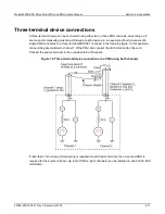
For a two-terminal device, refer to
Two-terminal device connections
(on page 2-9), using figure
"Two-terminal device connections to a PMU using both channels" as a guide.
•
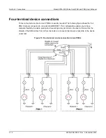
For a four-terminal device, use the
Four-terminal device connections
(on page 2-12) to two PMUs
(on page 2-15) four-terminal figure as a guide (as applicable). This
cabling approach permits the low-side measurement approach described in
(on page 3-35).


