Model 4200A-SCS Pulse Card (PGU and PMU) User's Manual
Section 2: Connections
4200A-PMU-900-01 Rev. A December 2020
2-7
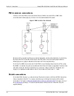
With an RPM installed, never make connections directly to any of the SMA connectors (CH1
and CH2) on the PMU. This may result in damage to the PMU or DUT, or may produce corrupt
data.
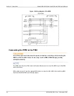
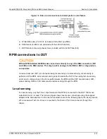
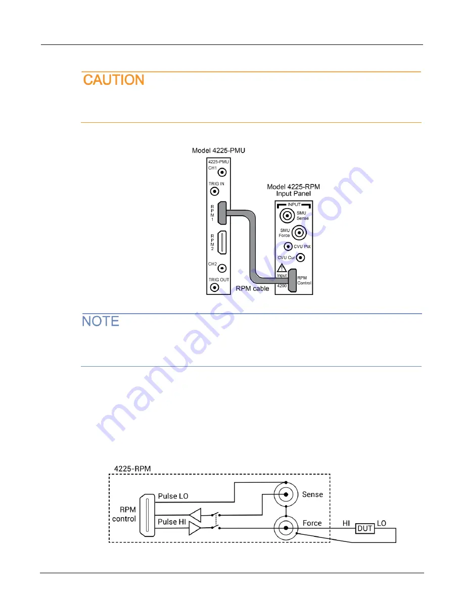
Figure 6: PMU connection to the RPM
After connecting or removing an RPM, always perform the “Update the RPM configuration” in
Model
4200A-SCS Setup and Maintenance
procedure to ensure that KCon accurately represents the
present 4200A-SCS hardware configuration.
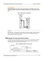
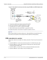
RPM diagrams for local and remote sensing
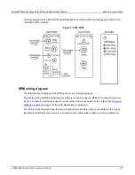
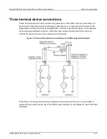
The following figure shows the diagram for local sensing. The center conductor of the Force triaxial
connector is connected to the high side of the device under test (DUT) while the outer shield is
connected to DUT LO. The Sense connector is not used.
Figure 7: RPM wiring diagram for local sensing

