Model 4200A-SCS Pulse Card (PGU and PMU) User's Manual
Section 2: Connections
4200A-PMU-900-01 Rev. A December 2020
2-25
LLEC maintains even voltage spacing
Another advantage of using LLEC is that it maintains even voltage spacing during the test. For
example, if the pulse sweep uses 250 mV steps, DUT voltage and current measurements will be
performed at every 250 mV step. Data that is generated using even voltage spacing is ready to be fed
into a mathematical model.
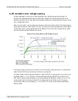
When not using LLEC, uneven voltage spacing may result due to load-line effect. The following figure
shows load-line effect on a FET family of curves. The blue curves were generated with LLEC enabled
and the green curves were generated with LLEC disabled. The Vg was been increased for the green
curves to provide separation between the curves.
Figure 23: Load-line effect on FET family of curves
In the previous figure, each blue curve (LLEC on) is the result of a sweep from 0 to 6 V using 250 mV
steps. Notice that the 24 pulse-measure points are evenly spaced.
The same sweep is used to generate the green curves (LLEC off). The best green curve is the one at
the bottom (bias V
g
= 2.5 V). However, load-line effect prevents the PMU from sourcing 6 V to the
DUT and the 24 pulse-measure points are not evenly spaced. Modifying the sweep to 0 to 6.5 V will
ensure that at least 6 V is output to the DUT, but voltage spacing will still be uneven. The green
curves for the other two bias voltages (V
g
= 3.0 V and 3.5 V) are even more adversely affected by
load-line effect.

