Section 3: Setting up PMUs and PGUs in Clarius
Model 4200A-SCS Pulse Card (PGU and PMU) User's Manual
3-38
4200A-PMU-900-01 Rev. A December 2020
PMU and RPM measure ranges are not source ranges
Unlike a source-measure unit (SMU), the PMU and RPM current measure ranges are measure
ranges only, not source and measure ranges. For example, the SMU 10 mA measure range has a
maximum source and measure value of ±10.5 mA, including the five percent overrange. The 10 mA
measure range of the PMU 10 V range has a maximum measurement of about ±10 mA, but the full
source capability of the 10 V source, which is ±200 mA. An alternate way to present this difference is
that the SMU range has a source compliance equal to the measurement limit, but the PMU and RPM
ranges have a source compliance larger than the measure range. Note that for the maximum PMU
current measure ranges (200 mA for the 10 V range, 800 mA for the 40 V range), the source limit is
the same as the measure limit, so the 200 mA and 800 mA ranges act similar to the SMU current
range.
This measure-only limit is necessary for the best performance of the pulse when using the PMU alone
or with the RPM. Generally, the purpose of a pulse measurement is to minimize the time required to
make a measurement in order to minimize device self-heating or some other time-based device
behavior.
To minimize the measurement time, the signal at the device under test (DUT) must get to the
specified voltage level and settle as quickly as possible. A key aspect of this goal is handling the
capacitive charging effects during the pulse transitions.
Since the interconnect and the DUT always have some capacitance, it is best to charge up this
capacitance as quickly as possible. This can be done by allowing the maximum amount of current to
flow into the capacitor during charging. This may cause an overflow for the measure range during
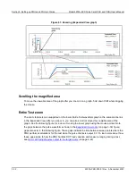
transitions, especially on the lower RPM measure ranges. Note that the measurement range cannot
be changed within a pulse, so a single measure range must be used for the entire pulse. The
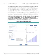
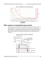
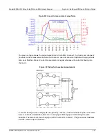
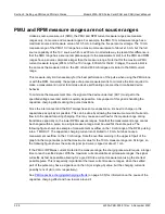
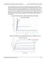
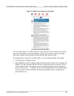
following figure shows an example of measurement overflow on the 10 mA range of the RPM, pulsing
into a 1 MΩ DUT. The capacitive charging current is not limited to 10 mA, but does cause a
measurement overflow on the 10 mA range. Note the overflow warning in the upper left part of the
graph (in the magenta box) and that maximum value for the 10 mA measure range is a bit larger, so
the following figure shows the current signal (red curve) clipped at about 11 mA.
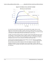
If the PMU or RPM was current limited to the measure range, the charging rate would require a longer
time to reach a settled signal. With the maximum current available at all measure ranges, the signal
will settle as fast as possible, allowing for a good DC-like current measurement using the shortest
possible pulse. This is especially important at the lower current measure ranges, when the settled
part of the pulse may have a signal level in the nA (or single μA) value, but the charging current is
possibly tens of μA (or mA, respectively).
PMU capacitive charging/discharging effects
(on page 3-35) for information on the cause of the
capacitive charging effect and how to work around it.

