


List of Illustrations
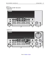
Figure 1-1
1-5
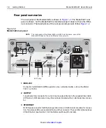
Figure 1-2
1-8
Figure 1-3
Figure 2-1
2-2
Figure 2-2
2-3
Figure 2-3
2-4
Figure 2-4
Output configurations – triax inner shield connected to Output Low ................
2-5
Figure 2-5
Output configurations – triax inner shield connected to Cable Guard ...............
2-6
Figure 2-6
Figure 2-7
Figure 2-8
2-11
Figure 2-9
Cable Guard connections – triax inner shield connected to Cable Guard ........
2-11
Figure 2-10
Connections for noise shield, safety shield, and guarding ................................
Figure 3-1
3-5
Figure 3-2
Source and compliance editing – Model 6220 ...................................................
3-8
Figure 3-3
Source and compliance editing – Model 6221 .................................................
Figure 4-1
4-3
Delta, Pulse Delta, and Differential Conductance
Figure 5-1
Delta, Pulse Delta, and Differential Conductance measurements ......................
5-3
Figure 5-2
System configurations for Delta, Pulse Delta, and Differential Conductance ....
5-5
Figure 5-3
System connections – stand-alone operation ......................................................
5-6
Figure 5-4
System connections – PC control of Model 622x ..............................................
5-7
Figure 5-5
5-8
Figure 5-6
Figure 5-7
Pulse Delta 3-point measurement technique .....................................................
Figure 5-8
Figure 5-9
Figure 5-10
Differential Conductance measurement process ...............................................
Averaging Filter, Math, and Buffer
Figure 6-1
6-9
Summary of Contents for 6220 DC
Page 2: ......
Page 4: ......
Page 6: ......
Page 16: ......
Page 36: ...1 20 Getting Started Model 6220 6221 User s Manual Return to Section 1 topics...
Page 131: ...6 10 Averaging Filter Math and Buffer Model 6220 6221 User s Manual Return to Section 6 topics...
Page 148: ...A Specifications...
Page 167: ......
Page 169: ......
Page 170: ......


