Service Information
5-3
One method to make instrument connections to the switch
card is to hard-wire a 96-pin female DIN connector and then
mate it to the connector on the Model 7036. Shorting con-
nections can also be done at the connector. The connector in
the Model 7011-KIT-R connection kit (see Table 3-2) can be
used for this purpose. Pin identification for the multi-pin
connector for the relay card is provided by Figure 3-1 and
Table 3-1.
WARNING
When wiring a connector, do not leave
any exposed wires. No conductive part
of the circuit may be exposed. Properly
cover the conductive parts, or death by
electric shock may occur.
CAUTION
After making solder connections to a
connector, remove solder flux as
explained at the beginning of this sec-
tion. Failure to clean the solder connec-
tions could result in degraded
performance, preventing the card from
passing verification tests.
Before pre-wiring any connector plugs, study the following
test procedures to fully understand the connection
requirements.
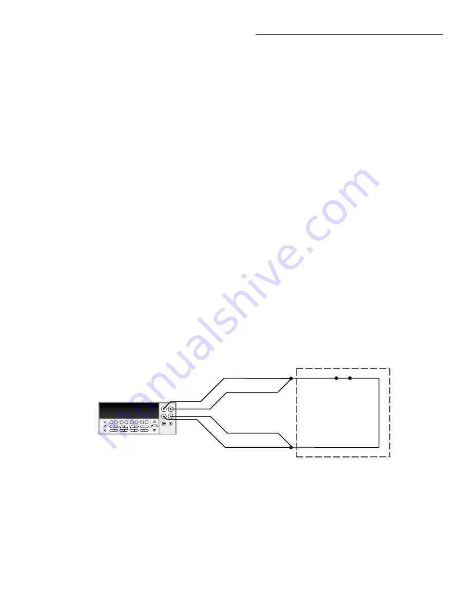
Channel resistance tests
Referring to Figure 5-1, perform the following steps to verify
that each contact of every relay is closing properly and that
the resistance is within specification
1. Turn the Model 7001/7002 off if it is on.
2. Set the Model 2000 to the 100
Ω
range and connect four
test leads to the INPUT and SENSE
Ω
4 WIRE input.
3. Short the four test leads together and zero the Model
2000. Leave zero enabled for the entire test.
4. Connect INPUT HI and SENSE
Ω
4 WIRE HI of the
Model 2000 to the input (IN) terminal of Channel 1 as
shown in Figure 5-1.
5. Connect INPUT LO and SENSE
Ω
4 WIRE LO to the
output (OUT) terminal of Channel 1.
6. With the card installed in slot 1 (CARD 1) of the main-
frame, turn on the Model 7001/7002 and program it to
close channel 1!1 (Slot 1, Channel 1). Verify that the
resistance of this channel is <1
Ω
.
7. Repeat the basic procedure of steps 1 through 6 to test
the rest of the channels of the Model 7036 relay switch
card. Remember to close the channel that the Model
2000 is connected to.
Figure 5-1
Channel resistance testing
HI
LO
POWER
7036
IN
OUT
Each Channel:
Path Resistance Test
Model 2000
(Measure 4-Wire Ohms)
Sense
Ω
4 Wire HI
Input HI
Input LO
Sense
Ω
4 Wire LO


