Card Connections and Installation
3-2
If a card becomes contaminated, it should be thoroughly
cleaned as explained in Section 5.
WARNING
The following connection infor-
mation is intended to be used by
qualified service personnel. Fail-
ure to recognize and observe
standard
safety
precautions
could result in personal injury or
death.
Multi-pin (mass termination)
connections
Since connections to external circuitry are made at the 96-pin
male DIN bulkhead connector, there is no need to separate
the connector card from the relay card. If the connector card
is separated from the relay card, carefully mate them
together and install the supplied 4-40 screw to secure the
cards. Make sure to handle the cards by the edges and shields
to avoid contamination.
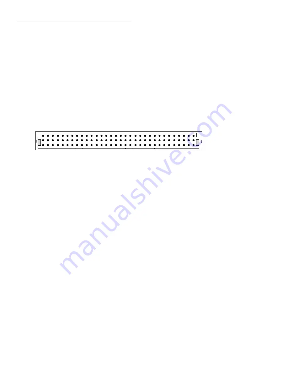
Terminal identification for the DIN connector of the multi-
pin connector card is provided by Figure 3-1 and Table 3-1.
This connector will mate to a 96-pin female DIN connector.
Figure 3-1
Multi-pin connector card terminal identificatio
View pin side
of connector
32 31 30 29 28 27 26 25 24 23 22 21 20 19 18 17 16 15 14 13 12 11 10 9 8 7 6 5 4 3 2 1
a
b
c


