background image

Summary of Contents for 7057A

Page 1: ...SERVICE CENTER REPAIRS Experienced engineers and technicians on staff at our full service in house repair center WE BUY USED EQUIPM Sell your excess un We also offer credit www artisantg com REMOTE I...

Page 2: ...KEITHLEY INSTRUMENTS Model 7057A Thermocouple Scanner Card Instruction Manual Contains Operating and Servicing Information Publication Date January 1992 Document Number 7057A 901 01 Rev D...

Page 3: ...AND EXCLUSIVE REMEDIES NEITHER KEITHLEY INSTRUMENTS INC NOR ANY OF ITS EMPLOYEES SHALL BE LIABLE FOR ANY DIRECT INDIRECT SPECIAL INCIDENTAL OR CONSEQUENTIAL DAMAGES ARISING OUT OF THE USE OF ITS INST...

Page 4: ...ctor jacks or test fixtures 111c American National Standards Institute ANSI states that a shock hazard exists when voltage levels greater than 30V RMS 42 4V peak or 60VDC are present Agood safety prac...

Page 5: ...ontact with these voltages TI1c WARNING heading in a manual explains dangers that might result in personal injury or death Always read the associated infonnation very carefully before performing the i...

Page 6: ...ettling TEMPERATURE REFERENCE Thermistor in a linearized bridge REFERENCE OUTPUT 1 mV 0 c OmV at 30 C REFERENCE ACCURACY 0 26 C 110 c to 35 C 0 5 C 0 C to 10 c and 35 C to 60 C WARM UP TIME 1 Hour to...

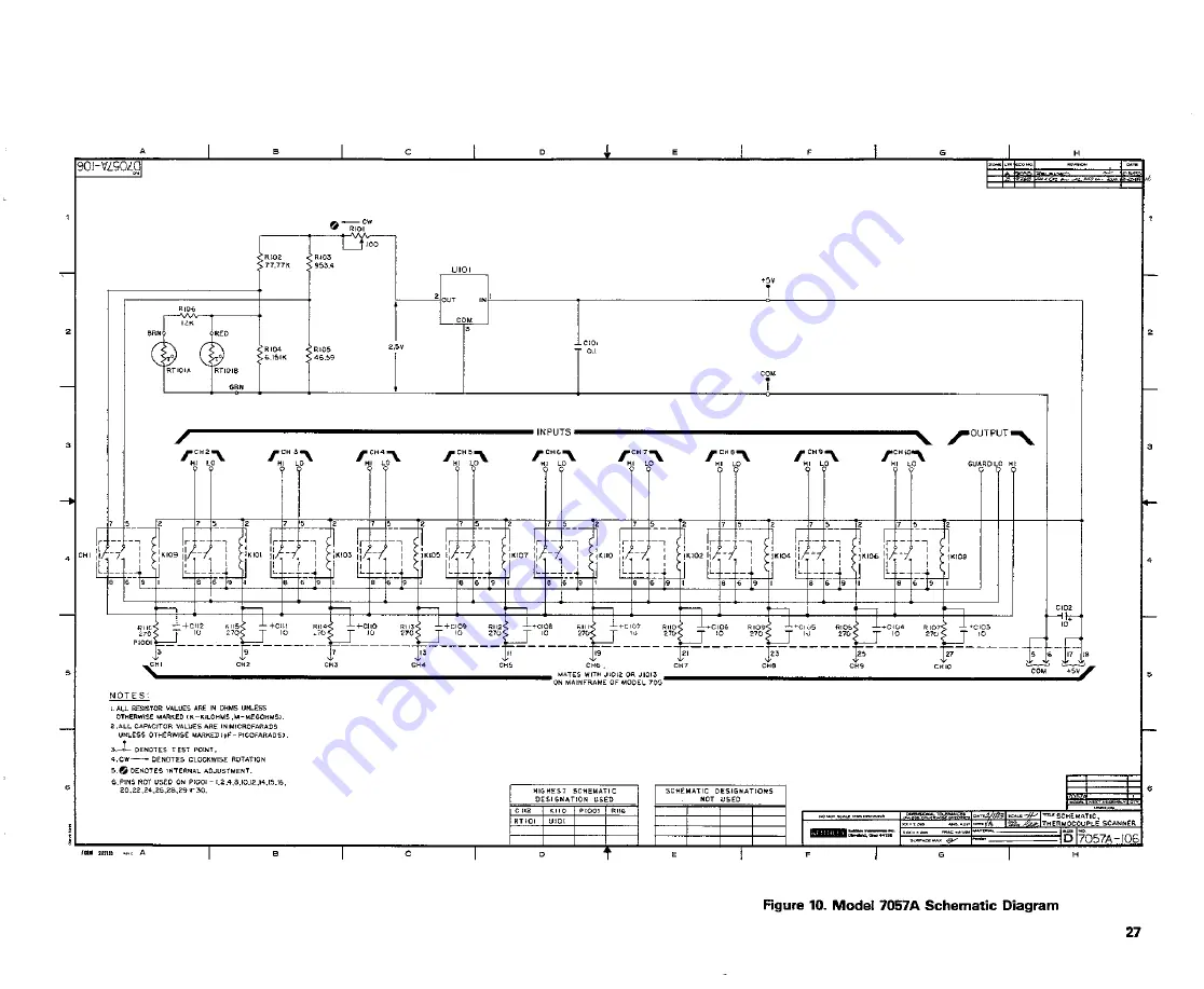
Page 7: ...LE PARTS 4 1 Introduction 23 4 2 Replaceable Parts 23 4 3 Ordering Information 23 4 4 Factory Seivice 23 4 5 Component Layout and Schematic Diagram 23 LIST OF FIGURES 1 Typical Thermocouple Connection...

Page 8: ...7057A uses 2 pole form A contacts for switching of signals up to 35V peak or 100mA peak Input and output connections are msde through the rear panel of the scanner mainframe using 4 screw terminals o...

Page 9: ...om a non isolated internal supply with jumper provisions for an external isolated supply A Input and output connections are made to the screw terminals shown in Figure 1 B Signal path resistance inclu...

Page 10: ...cally repeatable to within a few hundred nanovolts each time the channel is selected That is every time a channel is selected and allowed to stabilize for a period of time the channel will exhibit the...

Page 11: ...that the number of copper to copper junctions is at a minimum and therefore unnecessary thermal effects are avoided Figure 4 shows the method of continuous board to board connections ANALOG SIGNAL HI...

Page 12: ...ine the reference junction voltage E2 either from thermocouple reference tables or by the calculation 2 o A1 T 11ir2 a3T3 a4r4 where T T2 as detennined in step 1 above is expressed in microvolts The c...

Page 13: ...ovolts Calculate voltage E1 E E2 v X 10 6 E microvolts Calculate equivalent T a0 a1E1 a2E21 T1 CI temperature T 8381 84E41 2 7 SWITCH TERMINOLOGY Throughout this manual the terminology Form A is used...

Page 14: ...2077351 3 2 5723104 6 8 3681057 5 0061921 2 9 4591354 O 9 7986687 4 2 3967559 6 7 8837971 1 4352322 3 2 9873073 0 6 9951678 3 1 8986036 6 6 5006637 1 3054176 3 3 4129348 0 6 4741403 3 1 6163524 6 7 9...

Page 15: ...437 0 1 0322002 5 4122671 O 4 9347196 Exp Argument Exp 5 2 7849728 9 5 1 3626587 9 6 6 5660913 10 6 3 8981279 10 6 3 1267454 10 6 1 2643267 11 6 3 9224680 11 6 1 0845801 11 6 1 7334256 10 6 8 3038098...

Page 16: ...O 8 3100314 1 9442383 2 1 7913090 1 5014129 2 9 5376167 1 3844426 2 2 0889531 a3 Exp Argument Exp 2 1 1295306 5 3 7 1346883 6 3 3 7539447 6 3 1 8683292 6 3 1 2385309 6 3 7 5039035 7 4 2 5536988 6 4 2...

Page 17: ...1 5 6190639 2 6747958 O 2 2334214 a3 Exp Argument Exp 5 2 5404935 9 5 1 2610922 9 6 6 2073358 10 6 3 8266182 10 6 3 1420473 10 6 8 5173702 11 6 3 9276248 11 6 4 5164488 11 6 1 3863582 10 6 7 4538667...

Page 18: ...5749253 2 7380621 O 1 1375302 2 4673839 1 5 9050303 Exp Argument Exp Argument 3 5 6339756 7 1 1808558 3 5 9963592 7 9 7041131 3 5 7165679 7 1 0838193 3 3 3057924 7 2 0018428 3 9 1094186 8 2 8098361 3...

Page 19: ...8 9696912 6 1 5828913 1 7 0050689 6 1 4979551 1 5 7276293 6 a3 Argument Exp Argument 1 8053618 7 1 9719121 6 8254996 8 5 1002233 2 2187592 8 1 0678514 1 0792281 8 3 9111456 7 3717195 9 2 2913665 8 24...

Page 20: ...2 4 1877018 5 8637565 1 4 6720025 03 Exp Argument Exp 2 5 2421843 5 2 5 0637772 5 5 5 9506564 5 2 5 6288941 5 2 5 2870656 5 2 4 7821793 5 2 2 9769494 5 2 2 9237913 5 1 3 1228607 4 2 1 4438022 5 Argum...

Page 21: ...7013068 Exp Argument Exp Argument 6 1 4930918 9 8 7987588 6 1 9577799 10 1 6696298 7 6 9795810 12 5 1105852 7 4 6512717 12 4 1805785 7 5 4809314 12 5 7669892 7 1 8600342 12 8 5537337 8 5 6361365 13 1...

Page 22: ...7 2 3 6470921 5 0373743 1 3 0167011 Exp Argument Exp 2 6 3493968 5 2 6 9936031 5 2 2 2198295 5 2 6 5666305 5 2 6 7556436 5 2 4 2235982 5 2 3 1325181 5 1 1 3184454 4 2 2 2171472 5 1 4 2749984 4 1 2 702...

Page 23: ...2 1 7177773 Exp Argument Exp 6 2 5278593 10 7 1 2443997 11 7 3 9094347 12 7 7 8m919 12 7 8 3683958 12 7 3 7084018 12 8 2 4644023 12 7 1 3997013 11 7 2 5945419 12 6 2 1962321 11 6 2 1771293 11 Argumen...

Page 24: ...075276 1 1 4576419 3 9448872 1 2 4548362 SJ Exp Argument Exp 2 9 1607995 5 2 1 1488433 4 2 4 3081993 5 3 8 5714137 6 4 1 2525700 5 3 4 2015132 6 2 2 4734437 5 3 8 7444446 6 2 3 3517324 5 3 1 0989249 5...

Page 25: ...995 3 8 2516607 Exp Argument Exp 5 4 2824995 9 6 6 8203073 10 7 2 5720615 11 8 3 8825620 12 9 3 6276965 12 8 5 5358209 13 7 6 5075717 12 8 1 3269743 12 7 8 5482602 12 7 4 8782826 12 7 1 3558849 11 Arg...

Page 26: ...n selected temperature ranges The expansion is of the form E ao a1T a2T2 a3T3 a4T4 where Eis in microvolts and Tis in degrees Celsius Type T Thermocouples Temperature Range C I Quartic Equation 270 to...

Page 27: ...Allow to stabilize and note the difference at 30 C The difference should be less than 2 C 3 4 CHANNEL ISOLATION A Thls test measures the leakage resistance between two channels on the board One chann...

Page 28: ...ainframe and set the Model 705 to the Channel mode Channel 2 and the Step mode D Set the electrometerto Amps and program the Model 230 to output 100V Take the electrometer out of ZERO CHECK E Take the...

Page 29: ...t parts contact your Keithley representative of the factory See the inside front cover for addresses When ordering include the following information 1 Instrument Model Number 2 Instrument Serial Numbe...

Page 30: ...R 260 6 151k Wirewound R105 Resistor 46 590 0 02 W R 260 46 59 Wirewound R106 Resistor 12k0 1 W Metal Film R 168 12k R107 Resistor 2700 5 W1 R 76 270 R116 Composition RT101 Thermistor RT 4 U101 Low D...

Page 31: ...Figure 9 Model 7057A Component Location Diagram 25...

Page 32: ...U 270 10 27 10 PIOOIF________F_______17 1 3 I I 19______ 2 F 3 2 27 f16Ft CH I CH2 CH 3 CH4 CH5 Cf 6 CH7 CH9 CH9 C 110 ____ c AJ i 2M 6i o t5 COM sv NOTES LALL RESISTOR VALUES ARE IN OHMS Ut l 55 OTHE...

Page 33: ...or outpu circle ooe Drift 0Um ble to um OCmrnble OW llnotreadappliedln 1111 OOverloari 0Cahbratmn only o a rcqui 00 OCerlifica e of Calibration required atlach any idrldiona she as mxe sm 1 Oatecked a...

Page 34: ...GREAT BRITAfN JAF N Nlll1l IU M OS TA lWAN Kol M y N nimtnl I it ll lty onlo Kol Blcy n f KolU leyln INl n Kel M y rnr IC l ld t 11 m l 45 lOI Z W fa c 15 l 247 l elW ff nftaV Jw Urv W l Oi lv 51 j F...

Page 35: ...SERVICE CENTER REPAIRS Experienced engineers and technicians on staff at our full service in house repair center WE BUY USED EQUIPM Sell your excess un We also offer credit www artisantg com REMOTE I...

Reviews: