Model 7701
17
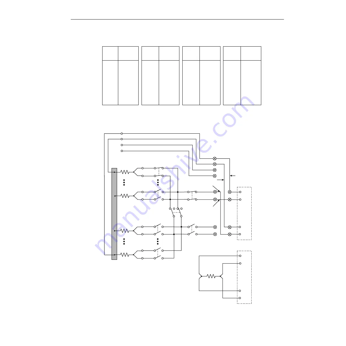
In
, channels 1 and 35 are closed to test DUT 1. The test for the other DUTs is similar except
that different measurement channels are closed. Closed channels for each DUT test are listed as follows:
Figure 12
Common-side 4-wire test system (multiple channel operation)
Tested
Device
Closed
Channels
Tested
Device
Closed
Channels
Tested
Device
Closed
Channels
Tested
Device
Closed
Channels
DUT 1 1 and 35
DUT 9
9 and 35
DUT 17 17 and 35
DUT 25 25 and 35
DUT 2 2 and 35
DUT 10 10 and 35
DUT 18 18 and 35
DUT 26 26 and 35
DUT 3 3 and 35
DUT 11 11 and 35
DUT 19 19 and 35
DUT 27 27 and 35
DUT 4 4 and 35
DUT 12 12 and 35
DUT 20 20 and 35
DUT 28 28 and 35
DUT 5 5 and 35
DUT 13 13 and 35
DUT 21 21 and 35
DUT 29 29 and 35
DUT 6 6 and 35
DUT 14 14 and 35
DUT 22 22 and 35
DUT 30 30 and 35
DUT 7 7 and 35
DUT 15 15 and 35
DUT 23 23 and 35
DUT 31 31 and 35
DUT 8 8 and 35
DUT 16 16 and 35
DUT 24 24 and 35
DUT 32 32 and 35
Ch 1
DUT
DUT1
DUT1
DUT3
DUT
P25
P24
P1
P12
HI
LO
Ch 16
HI
LO
(Ch 2–15)
Ch 17
Ch 32
(Ch 18–31)
HI
LO
Sense
HI
LO
Input
Ch 33
(Open)
Ch 35
Ch 34
HI
LO
HI
LO
Sense LO
Input LO
DMM
Sense HI
Input HI
HI
LO
Sense
HI
LO
Input
DMM
Equivalent Circuit
Multiple channels 1 and 35 closed to perform
4-wire measurement on DUTI.
Note: Installation of the four screw terminal jumpers
(A through D) is shown in Figure 13.
Common-Side
Bus
Jumper A
Jumper B
Jumper C
Jumper D


