6
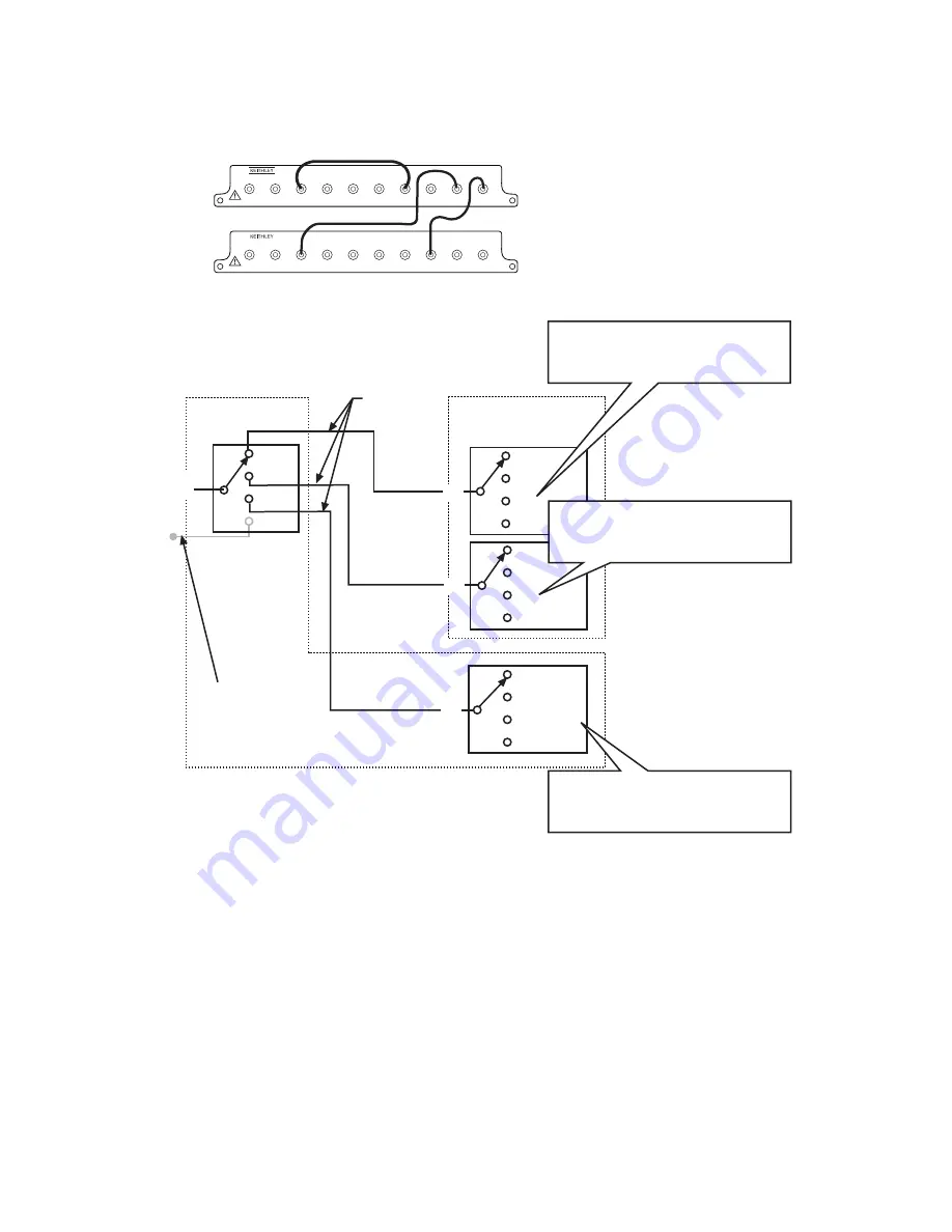
Figure 3
1
××××
12 MUX expansion
CH7
CH1
CH2
OUT A
CH3
CH4
CH5
CH8
CH6
OUT B
7711
CH7
CH1
CH2
OUT A
CH3
CH4
CH5
CH8
CH6
OUT B
7711
SLOT 1
SLOT 2
NOTE: The simplified schematic is shown in the
power up state (Channels 1 and 5 are
closed for cards in slots 1 and 2).
Grayed channels are not used in this
1
×
12 SP12T MUX.
OUT B
7711/7712
Slot 1
7711/7712
Slot 2
Ch1
Ch2
Ch3
Ch4
OUT A
OUT A
Ch1
Ch2
Ch3
Ch4
Ch8
Ch6
Ch7
Ch5
S46-SMA-0.5
Cable (Qty 3)
Ch5 (Ch9)
Ch6 (Ch10)
Ch7 (Ch11)
Ch8 (Ch12)
Terminate this
unused channel
in bank 1 with a 50
Ω
load or an unconnected
S46-SMA-0.5 cable.
OUT B
ROUTe:MULTiple:CLOSe(@101,203)
To close to this crosspoint (CH3) send:
ROUTe:MULTiple:CLOSe(@102,207)
To close to this crosspoint (CH7) send:
NOTE: Channels 5-8 on the 7711/7712
in slot 1 correspond to crosspoints
Channels 9-12 of the 1
×
12 SP12T
MUX.
ROUTe:MULTiple:CLOSe(@103,107)
To close to this crosspoint (CH11) send:
>>
>>
>>
>>
Summary of Contents for 7711
Page 30: ...26 Figure 12 Model 7711 component layout...
Page 31: ...27 Figure 13 Model 7712 component layout...
Page 37: ......


