10
Wiring procedure
WARNING
Do not exceed the maximum specifications for the Model 7711/7712 module. Refer to
Appendix A for specifications.
The default closed channels are 1 and 5 — the lowest number in each bank. At power-up, the lowest numbered channel in each
bank will always be closed. If using a saved setup that calls for another channel to be closed, the card will be switched to that
channel but only after the firmware has finished "waking up." Therefore, the lowest channel will ALWAYS be closed for at
least a brief time at power-up. The user needs to verify that nothing is connected to the lowest channel in each bank that could
be damaged.
The connectors on the card are standard SMA type connectors. When making or breaking connections, use a torque wrench to
produce mating torque of 0.9 N•m (8in•lbs).
NOTE
Use a box-spanner torque wrench similar to Suhner Type 74 Z-1-0-21, Identification number
543130. This wrench is for SMA connectors with a 1.00 N•m torque with 8.0mm (0.315 in.) across
the flats.
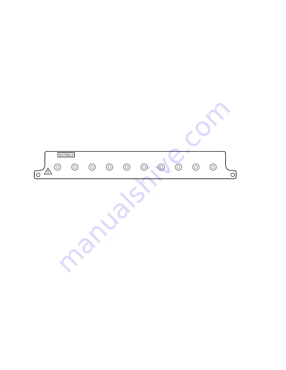
Figure 6
Model 7711/7712 channel connections
WARNING
Do not touch live RF (radio frequency) conductors, even at low voltages! RF behaves
differently than DC or low frequency AC. Low voltage RF can cause severe burns. RF
signals spread out over body areas generating substantial currents at the points of
contact with RF conductors.
Make all connections using correct wire size. If BNC connections are required, use the SMA to BNC adapter cables (see
Available accessories on page 2
).
Specifications
Full Model 7711/7712 specifications are included at the end of this User Guide.
CH7
CH1
CH2
OUT A
CH3
CH4
CH5
CH8
CH6
OUT B
7711
Summary of Contents for 7711
Page 30: ...26 Figure 12 Model 7711 component layout...
Page 31: ...27 Figure 13 Model 7712 component layout...
Page 37: ......


