24
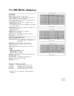
Cross-talk
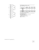
1. Connect cables as shown in
Figure 11
(Channel 1 to port 1 and channel 2 to port 2, 50
Ω
load on OUT A).
2. Close channel 1 (all other channels will open).
3. Display Log Magnitude plot on the network analyzer.
4. Select S12 measurement.
5. Verify specifications.
For the Model 7711, verify at 100MHz, 500MHz, 1GHz, 1.5GHz, and 2GHz.
For the Model 7712, verify at 500MHz, 1GHz, 2.5GHz, and 3.5GHz.
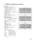
Refer to the Ch-Ch cross-talk section of the Model 7711 or 7712 specifications values for acceptable limits.
6. Repeat procedure for remaining channels in both banks. There are six possible combinations for each bank of 4 channels
(combinations in bank 1: 1-2, 1-3, 1-4, 2-3, 3-4). When verifying cross-talk in the second bank, connect the 50
Ω
load on
OUT B.
Figure 11
Cross-talk verification
Replaceable parts
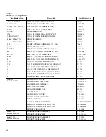
This section contains replacement parts information and the component layout drawing for the Model 7711/7712.
Parts list
Replaceable parts for the Model 7711/7712 are listed in
Table 9
.
Network analyzer
Port 1 Port 2
50
Ω
load
Ch1
Ch2
OUT A
Ch3
Ch4
Ch5
Ch6
OUT B
Ch7
Ch8
Model 7711/7712
Summary of Contents for 7711
Page 30: ...26 Figure 12 Model 7711 component layout...
Page 31: ...27 Figure 13 Model 7712 component layout...
Page 37: ......


