Section 8: Mixed function multi-channel scanning
DAQ6510 Data Acquisition / Multimeter System User's Manual
8-2
DAQ6510-900-01Rev. A / April 2018
Device connections
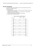
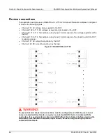
This application example uses a DAQ6510 with a 7700, 20-channel differential multiplexer configured
to monitor the following signals:
•
Channel 101: AC voltage being supplied to the DUT.
•
Channels 102 to 110: DC voltages at several points located on the DUT.
•
Channels 111 to 112: Temperature (using Type-K thermocouples) of two voltage regulators within
the DUT.
•
Channels 113 to 114: Temperature (using Type-K thermocouples) of two loads to which the DUT
is supplying power.
•
Channel 121: AC current being drawn by the DUT.
•
Channel 122: DC current being drawn by the load.
Figure 41: DAQ6510 Model 7700
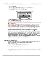
To prevent electric shock, test connections must be configured such that the user cannot
come in contact with test leads or any device under test (DUT) that is in contact with the
conductors. It is good practice to disconnect DUTs from the instrument before powering the
instrument. Safe installation requires proper shields, barriers, and grounding to prevent
contact with test leads.


