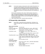
Quick Start Guide
Integra Series 35
Input connections and measurements
WARNING
The following summary on Model 7700 input connections is for
informational use only. It is only intended to show how a an
input signal is connected and routed through the switching
module to the mainframe DMM.
Module connections and installation into the mainframe are
only to be performed by qualified service personnel. For details
on these procedures, refer to the User’s Guide that is supplied
with the switching module.
CAUTION
To prevent damage to the switching module, do not exceed the
maximum signal levels listed in
The Model 7700 has 20 input channels (1 through 20) for volts, ohms, frequency,
period, and temperature measurements. It also has 2 channels for amps mea-
surements (channels 21 and 22).
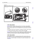
The Model 7700 switching module uses screw terminal blocks for test connections
to input circuits. The screw terminals are accessed by removing the top cover of
the module (see
A). Turn the locking screw to unlock and open the cover.
B shows an example of how the module is to be wired. Use insulated
wire (up 20 AWG) for connections. When replacing the cover, push in the screw to
lock.
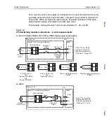
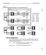
and
show the various input connections and how the input
signal is routed through the switching module to the mainframe DMM.
Table 2
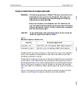
Maximum inputs for Model 7700
Channel
Maximum signal level
Channels 1- 20
300V DC or rms, 1A switched, 60W, 125VA maximum.
Channels 21 and 22
60V DC or rms, 3A switched, 60W, 125V maximum.
To
p
To
p
To
p
Summary of Contents for Integra 27 Series
Page 3: ......
Page 8: ...QuickStartGuide Integra Series...

