Quick Start Guide
Integra Series 5
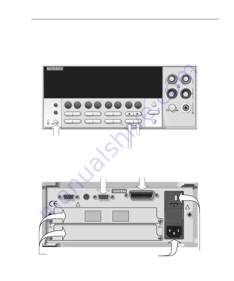
Front and rear panels (mainframe)
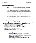
The front and rear panels of the Models 2700, 2701 and 2750 are shown in
. These illustrations show all controls and connectors.
Figure 2
Model 2700 front and rear panels
KEITHLEY
SLOT COVER
DIGITAL I/O
TRIG. LINK
RS232
WARNING:
NO INTERNAL OPERATOR SERVICABLE PARTS,SERVICE BY QUALIFIED PERSONNEL ONLY.
CAUTION:
FOR CONTINUED PROTECTION AGAINST FIRE HAZARD,REPLACE FUSE WITH SAME TYPE AND RATING.
MADE IN
U.S.A.
!
!
IEEE-488
SLT
2
SLT
1
F
!
F
Model 2700
Multimeter / Data Acquisition System
RANGE
F
500V
PEAK
FRONT/REAR
3A 250V
AMPS
HI
INPUT
LO
SENSE
Ω
4 WIRE
INPUTS
350V
PEAK
1000V
PEAK
AUTO
SHIFT
LOCAL
POWER
RANGE
R
EXIT
ENTER
DIGITS RATE
REL
FILTER
TRIG
EX TRIG
STORE RECALL
OPEN
DCV
DCI
MATH
O U T P U T
RATIO
ACV
ACI
Ω
2
Ω
4
FREQ
TEMP
CH AVG
CONT
PERIOD SENSOR
LIMITS
ON/OFF
DELAY
HOLD
SAVE
SETUP
CONFIG
HALT
TYPE
LSYNC
TEST
MONITOR
STEP
SCAN
OCOMP
CH-OFF
CARD
CLOSE
Integra Series
RS-232
GPIB
For
RS-232 communication
, connect
to serial port of computer using a
straight-through RS-232 cable (DB-9).
Do not use a null modem cable.
For
GPIB communication
, connect
to GPIB port of computer using an
IEEE-488 cable (Keithley 7007).
120
Window
shows
line voltage
setting
Using the
supplied line cord
, connect to a grounded
AC power outlet. The line voltage setting shown in
the window of the fuse holder must match line
the voltage at the AC power outlet.
Power switch
– Turn on the 2700 by pressing to the on (I)
position. To turn off, release the switch to the off (O) position.
Two slots
for Keithley
switching modules
GPIB
– Press SHIFT and then EXIT (GPIB) to access
menu. Use the edit keys to enable (ON) the GPIB and
set the address (ADDR).
Communications configuration:
RS-232
– Press SHIFT and then ENTER (RS-232) to
access menu. Use the edit keys to enable (ON)
RS-232, and set the terminator (TX TERM), FLOW
control, and BAUD rate.
To
p
To
p
To
p
Summary of Contents for Integra 27 Series
Page 3: ......
Page 8: ...QuickStartGuide Integra Series...


