Installation and Configuration
KPCI-3101 — KPCI-3104 Series User’s Manual
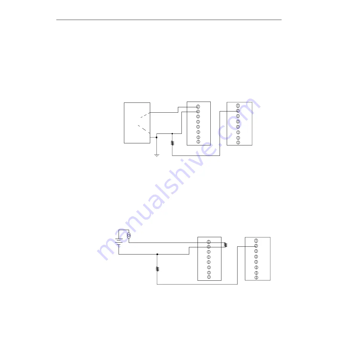
Note that since they measure the difference between the signals at the high (+) and low (
−
)
inputs, differential connections usually cancel any common-mode voltages, leaving only the sig-
nal. However, if you are using a grounded signal source and ground loop problems arise, connect
the differential signals to the STA-300 screw terminal panel as shown in
make sure that the low side of the signal (
−
) is connected to ground at the signal source, not at
the STA-300 screw terminal panel, and do not tie the two grounds together.
Figure 3-8
Connecting differential voltage inputs from a grounded signal source
(shown for channel 0)
Connecting current loop inputs
shows how to connect a current loop input (channel 0, in this case) to the STA-300
screw terminal panel.
Figure 3-9
Connecting current inputs (shown for channel 0)
TB18
Grounded
Signal
Source
+
-
TB1
TB2
Analog In 0
Analog In 0
Return
E
s
Signal Source
Ground V
g1
STA-300 Panel
Resistor R1 should be installed for bias
return in case the external ground is floating.
R1
Analog Ground
STA-300 Panel
TB1
Analog Input 0
Analog Input 0
Return
TB2
TB18
Analog Ground
4 to 20mA
+V
CC
R1
R9
Use current shunt resistor R9 to convert current to voltage;
250
Ω
for 4 to 20mA = 1 to 5V. The common-side of the
external loop supply must either connect to analog ground
or, if needed, to a bias return resistor (R1 in this case).
Summary of Contents for KPCI-3101 Series
Page 10: ...iv...
Page 15: ...1 Overview...
Page 21: ...2 Principles of Operation...
Page 53: ...3 Installation and Configuration...
Page 78: ...3 26 Installation and Configuration KPCI 3101 KPCI 3104 Series User s Manual...
Page 79: ...4 Testing the Board...
Page 82: ...4 4 Testing the Board KPCI 3101 KPCI 3104 Series User s Manual...
Page 83: ...5 Calibration...
Page 86: ...5 4 Calibration KPCI 3101 KPCI 3104 Series User s Manual...
Page 87: ...6 Troubleshooting...
Page 94: ...6 8 Troubleshooting KPCI 3101 KPCI 3104 Series User s Manual...
Page 95: ...A Specifications...
Page 107: ...B Connector Pin Assignments...
Page 111: ...C Systematic Problem Isolation...
Page 145: ...This page intentionally left blank...
Page 146: ...Keithley Instruments Inc 28775 Aurora Road Cleveland Ohio 44139 Printed in the U S A...


